Dual-Mode Piezoelectric/Magnetic Vibrational Energy Harvester

a piezoelectric and magnetic vibration technology, applied in the direction of generators/motors, mechanical equipment, machines/engines, etc., can solve the problems of poor battery energy efficiency, disproportionate amounts of hazardous waste, and harmful environmental impacts and product safety issues, so as to reduce the dependence on grid-supplied electricity, improve the overall electrical efficiency of the device power system, and reduce the effect of hazardous was

Active Publication Date: 2011-09-08
UNIV OF FLORIDA RES FOUNDATION INC
View PDF25 Cites 48 Cited by
  • Summary
  • Abstract
  • Description
  • Claims
  • Application Information

AI Technical Summary

Benefits of technology

[0008]Embodiments of the subject invention relate to a method and apparatus for vibrational energy harvesting. Specific embodiments can provide power to portable electronic devices. Embodiments of the subject invention relate to compact, hybrid power systems that use multi-mode vibrational energy-harvesting. Specific embodiments can be used to power portable electronic devices, such as a cellular telephone handset. Embodiments improve the overall electrical efficiency of the device power system and reduce the hazardous waste associated with powering the portable electronic device. Embodiments of the present invention implement vibrational energy-harvesting techniques to create compact, hybrid power systems that reduce or eliminate the dependence of grid-supplied electricity while simultaneously reducing the hazardous waste associated with battery disposal. Embodiments of the subject energy harvesting device merge two types of vibrational energy harvesters, namely piezoelectric and electromagnetic, into a single, multi-mode energy converter.

Problems solved by technology

For modern portable electronic devices, the use of secondary (rechargeable) batteries charged by grid-supplied battery rechargers is energy-inefficient, while the use of primary (single-use) batteries yields disproportionate amounts of hazardous waste.
Poor energy efficiency of batteries, especially for rechargeables, can have detrimental environmental impacts and product safety issues.
For example, while the power consumption of an individual device may be relatively small, the total power required to repeatedly recharge hundreds of millions of these devices is not.
Only 5% of this energy is actually used to power the phone, while the remaining 95% is wasted by inefficiencies in the charging of rechargeable batteries.
In addition, the batteries required to power these portable devices often contain potentially hazardous chemicals, such as mercury, lead, manganese, lithium, and cadmium.
These chemicals can contaminate the environment when not properly disposed.
Moreover, many of the batteries are prone to overheating, fire, and even explosion.
Despite increased efforts for recycling programs, most batteries end up in landfills.
Unfortunately, vibrational energy harvesting devices have not found widespread success, largely because of limited performance and poorly targeted applications.
In particular, the utility of many previously developed energy harvesters has been limited because the devices have been designed without regard to a particular application, often leading to good perfoimance on a laboratory bench, but no “real-world” application.
However, with reduced size scale, it has been quite challenging to achieve a mechanical resonance low enough to match the frequency range for naturally occurring vibrations (˜1 Hz-1 kHz).
This can limit their usefulness because naturally occurring vibrations usually have wide spectral content, and the primary vibration frequencies change in time.

Method used


Image

  • Dual-Mode Piezoelectric/Magnetic Vibrational Energy Harvester
  • Dual-Mode Piezoelectric/Magnetic Vibrational Energy Harvester
  • Dual-Mode Piezoelectric/Magnetic Vibrational Energy Harvester

Examples


Embodiment Construction

[0020]Embodiments of the present invention pertain to compact power sources for sensors, portable electronics, and battery-operated devices. Embodiments provide a dual-mode magnetic / piezoelectric energy harvesting structure. In an embodiment, an integrated structure is provided that may achieve a high power density. In addition, system level enhancements involving complementary voltage / current levels and impedances may be incorporated.

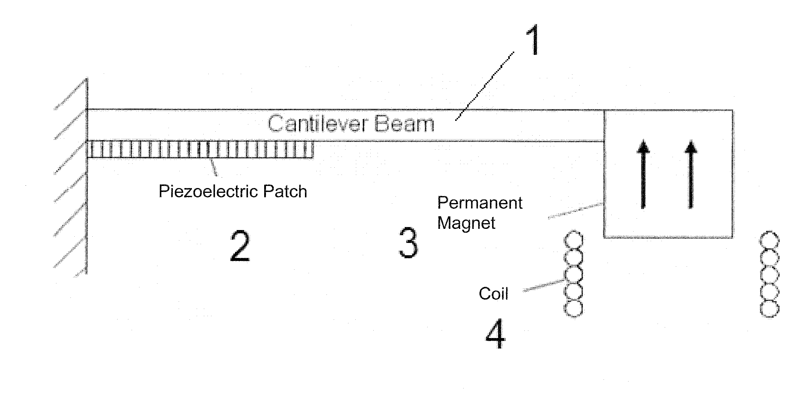
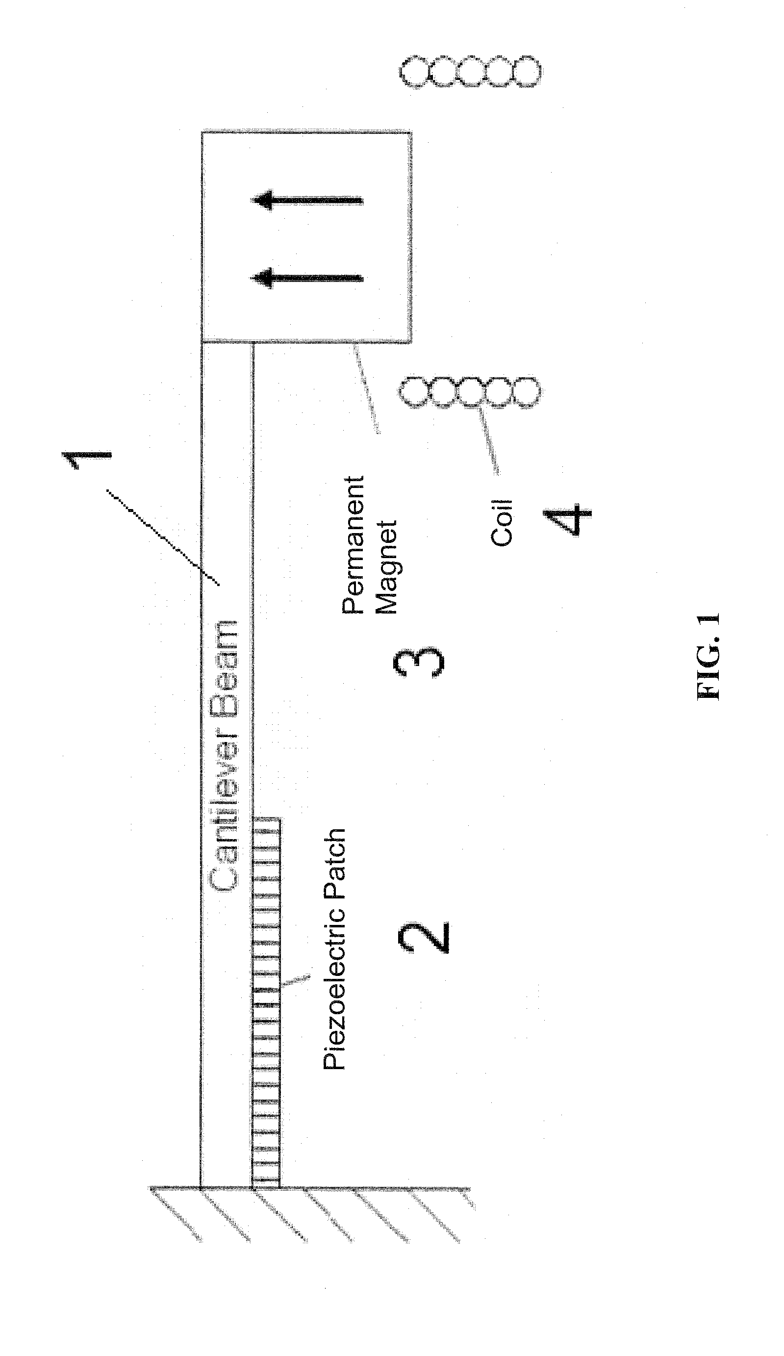
[0021]Embodiments of the present invention provide an energy harvesting structure that uses both piezoelectric and magnetic transduction schemes simultaneously. A specific embodiment of a vibrational energy harvester in accordance with the subject invention incorporates a body and a proof mass connected to the body via a flexible member. The proof mass moves with respect to the body via bending of the flexible member when the body is moved. A piezoelectric patch is attached to the flexible member such that the piezoelectric patch creates a voltage when...


PUM


Abstract

Embodiments of a vibrational energy harvester are provided. A vibrational energy harvester can include a translator layer sandwiched between two stator layers. The translator layer can include a plate having an array of magnets and two or more piezoelectric patches coupled to a tether beam attached to the plate. The stator layers can have a printed circuit board with multilayer electrical windings situated in a housing. In operation, vibration of the housing can result in bending of the piezoelectric patches coupled to the tether beam. This bending simultaneously results in a relative displacement of the translator, which causes a voltage potential in the piezoelectric patches, and a relative velocity between the translator and the stators, which induces a voltage potential in the stator coils. These voltage potentials generate an AC power, which can be converted to DC power through a rectification circuit incorporating passive and active conversion.

Description

CROSS-REFERENCE TO RELATED APPLICATION[0001]The present application claims the benefit of U.S. Provisional Application Ser. No. 60 / 973,339, filed Sep. 18, 2007, which is hereby incorporated by reference herein in its entirety, including any figures, tables, or drawings.BACKGROUND OF INVENTION[0002]Cellular phones, media players, and other high-performance portable electronics are becoming increasingly ubiquitous for business and personal use. Battery technologies have afforded major conveniences for a wide array of portable electronic products. Additionally, battery-powered power tools and home appliances are becoming more commonplace. These systems typically rely on high power density, secondary (rechargeable) batteries such as lithium-ion, nickel-metal-hydride, or nickel-cadmium. In contrast, low-power electronic devices, such as remote controls, medical devices, pagers, watches, and toys, typically use primary (single-use) alkaline manganese, mercuric oxide, silver oxide, or lith...

Claims


Application Information

Patent Timeline
Patent Type & Authority Applications(United States)
IPC IPC(8): F03G7/08
CPCH02K7/1892H02N2/186H02K35/02
Inventor ARNOLD, DAVID PATRICKNISHIDA, TOSHIKAZU
Owner UNIV OF FLORIDA RES FOUNDATION INC
Why Eureka
Try Eureka