Composite tubular product

a tubular product and composite technology, applied in the field of tubular elements, can solve the problems of material different problems, commercial difficulties in recovery, and immediate apparent enormity of technical problems, and achieve the effect of improving compatibility with the resin matrix

Inactive Publication Date: 2011-09-15
LOCHNAGAR CONSULTING
View PDF24 Cites 4 Cited by
  • Summary
  • Abstract
  • Description
  • Claims
  • Application Information

AI Technical Summary

Benefits of technology

[0021]Optionally these particles or equivalent are surface treated with a silane coupling agent (e.g. an epoxysilane) or similar primer to improve compatibility with the resin matrix of a GRP(GFK) winding making up the composite material surface.
[0022]Application of such particles is achievable by use of a gravity feed hopper in conjunction with a pneumatic device arranged to blow particles emerging from the hopper in a predetermined direction. The air flow generated can be used to convey particles into a shaped distribution nozzle for applying the particles to the GRP(GFK) resin matrix before it is fully cured to form the composite material surface. In this way a uniform surface or a patterned array of ceramic particles can be selectively generated upon the tubular by control of the distribution nozzle.
[0023]Control of air pressure and air flow rate allows control of the process, and use of a gate or valve on the hopper for throttling feed of the particles into the air stream also provides a further degree of control.

Problems solved by technology

Currently (2008), it is widely recognised that production of oil & gas from readily accessible fields is a matter of history and that prospects for discovery of virgin reservoirs of such resources lie offshore in coastal waters and in generally challenging sites.
The issue of deep drilling brings commercial difficulties in terms of recovery of the products, but more significantly complex technical difficulties in accessing the products in the first place.
When it is realised that the drill has to transit the depth of water before landing upon the surface to be drilled, the enormity of the technical issues is immediately apparent: for example the weight of the drill string alone is a significant factor in operating a drilling rig both in terms of function and safety issues.
Commonly the drill pipe is formed from steel, and although there have been some proposals to address the weight problem by adopting composite materials; such a switch in material manifests different problems.
It has been found that in order to match the strength of steel tubulars, the wall thickness of the corresponding composite has to increase markedly, but then there are losses in terms of properties recognised in steel such as ductility (flexibility) and durability (wear resistance).
A composite that is theoretically capable of carrying the tensile load may be unusable on account of liability to fracture in a heaving swell at sea or jarring in a hard formation, or due to inferior wear characteristics for repeated run-in and pull out trips.
An additional problem with costs for drilling operations lies in the expensive wear on the drill pipe as it is reciprocated (repeatedly run in and pulled out of the well) in order to extend its length by addition of further sections of drill pipe to extend drilling depth, or sometimes to replace it with a work string e.g. including a fishing tool to retrieve junk such as broken drill pipe etc.
Whereas it has been contemplated that wear can be mitigated to an extent by use of a hard facing material, this is contemplated around the upset region of metal drill pipe joints and is not considered to be a universal solution.
Equally, wear on casing has to be considered as a problem that arises especially during reciprocation of drill or other work strings.
Consequently, the return fluid passing up the annulus to surface around the drill string is loaded with abrasive drill cuttings which are detrimental to previously considered composite materials.
Therefore, until now, the various problems associated with metal tubulars that are subject to wear on external contact surfaces due to rotation and / or reciprocation within a borehole have not been adequately addressed by known composite products.

Method used


Image

  • Composite tubular product
  • Composite tubular product

Examples


Embodiment Construction

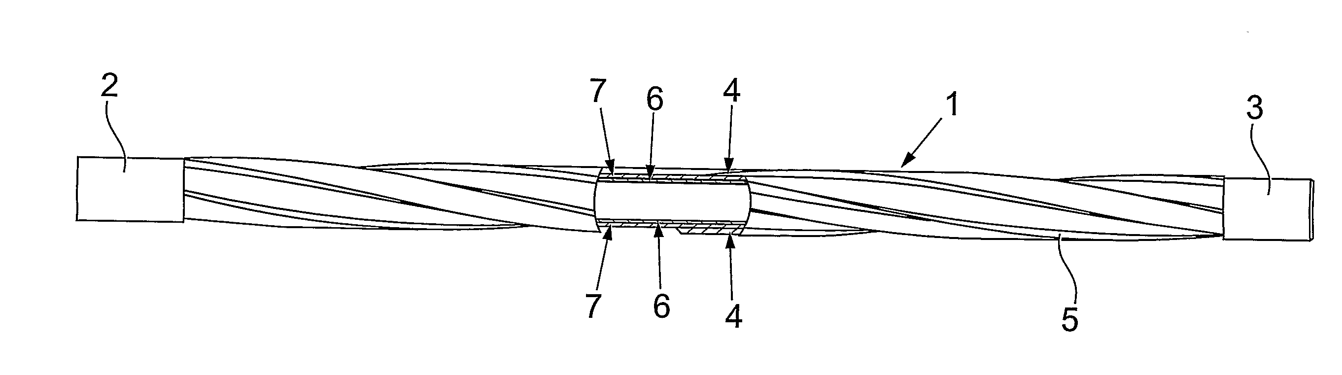
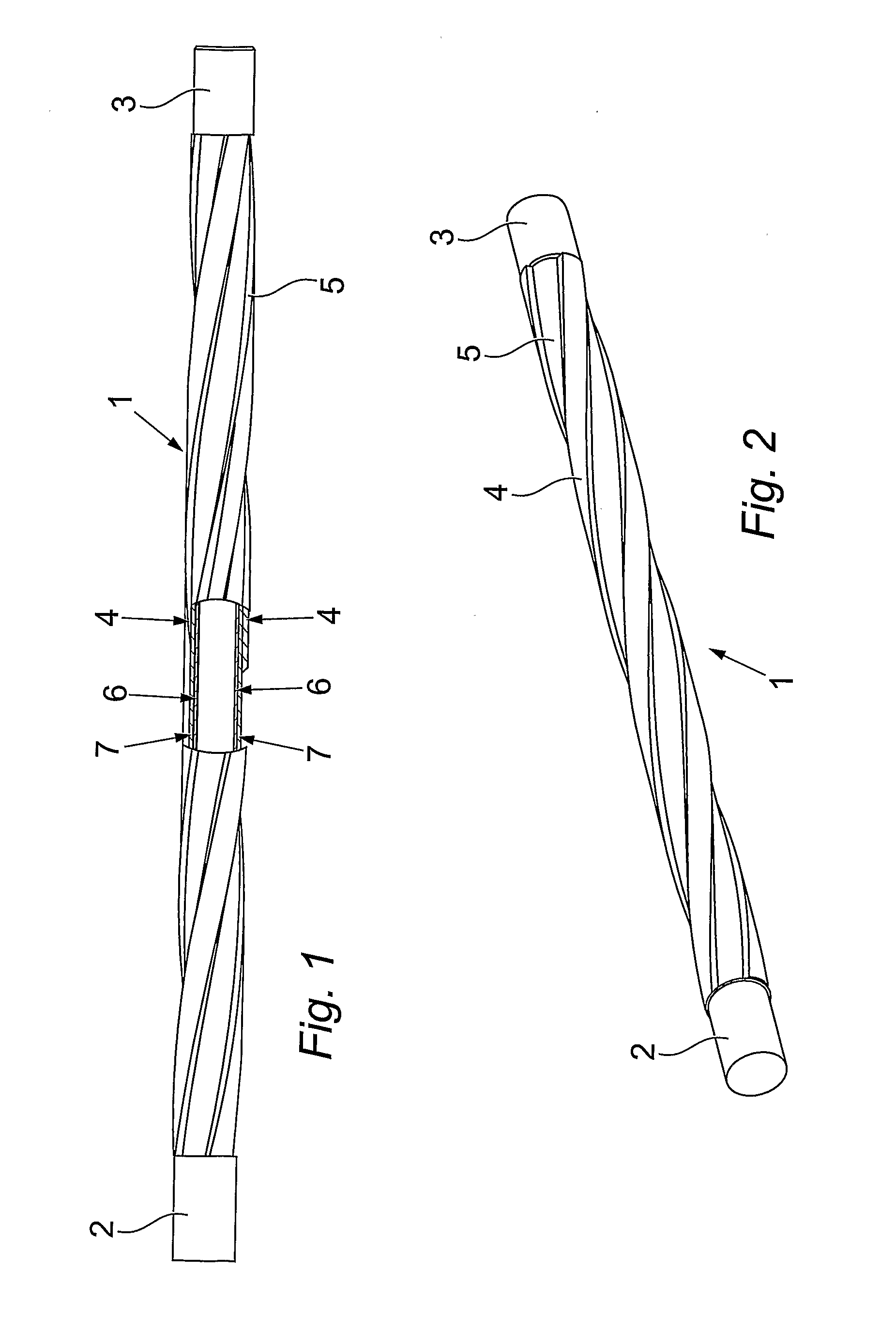
[0038]Referring to FIG. 1, an improved tubular is shown in the form of stand of drill pipe 1, that has traditional end coupling means in the form of box and pin ends 2, 3 respectively for use in forming tool joints in connecting into a drill string, and wear-resistant surface contact ribs 4, with flow-past channels 5 therebetween. The core of the drill pipe is a mandrel 6, which in this embodiment is a steel pipe, over which is applied a carbon fibre reinforcement material and bonding material 7 and which is built up to form the ribs 4. Ceramic beads (not shown) are introduced before the composite material is fully cured and generally form a random surface pattern of exposed ceramic smooth surfaces.

[0039]In a method of making such an improved tubular, a steel mandrel having traditional box and pin ends is mounted in a treatment booth, and reinforcement and bonding materials suitable for forming a durable composite are applied under composite material forming conditions.

[0040]Glass o...


PUM

PropertyMeasurementUnit
depthsaaaaaaaaaa
depthsaaaaaaaaaa
drill depthaaaaaaaaaa

Abstract

A tubular element (1) adapted for use downhole in drilling and oil & gas prospecting comprises a metallic mandrel (6) adapted to be connected (2,3) within a string of elongate elements, with a GRP(GFK) composite material (7) upon an outer surface of the mandrel in which a plurality of ceramic particles are partially embedded to present exposed contact surfaces in the formed composite material. The surface can be ribbed (4) with flow channels (5) therebetween. Suitable particles are of zirconium oxide, silicon nitride, cubic boron nitride, and mixtures of two or more thereof, whereby improvements in weight/strength ratio, fatigue endurance, increased torsional properties, with reduction of wear on the casing are obtained when such composite tubulars of the invention are used as drill pipe or work string sub-assembly elements.

Description

FIELD OF THE INVENTION[0001]This invention relates to tubular elements such as sections of drill pipe, work strings, sub assemblies, risers, rods and the like elongate elements adapted for use downhole in drilling and oil & gas prospecting and recovery (hereinafter “tubulars”).BACKGROUND TO THE INVENTION[0002]Currently (2008), it is widely recognised that production of oil & gas from readily accessible fields is a matter of history and that prospects for discovery of virgin reservoirs of such resources lie offshore in coastal waters and in generally challenging sites. The issue of deep drilling brings commercial difficulties in terms of recovery of the products, but more significantly complex technical difficulties in accessing the products in the first place. Towards the end of the last century off shore drilling into reservoirs at depths of 1300 feet was considered deep, but now it is not unusual to be penetrating wells under some 10,000 feet of ocean. Drill ships and platforms of...

Claims


Application Information

Patent Timeline
Patent Type & Authority Applications(United States)
IPC IPC(8): F16L11/00B65H81/08
CPCB29C70/025B29C70/32B29C70/64B29D24/00F16L57/06B29L2023/22E21B17/1085E21B17/22B29K2709/02
Inventor CAMERON, DUNCAN
Owner LOCHNAGAR CONSULTING
Why Eureka
Try Eureka