

Spray foams with fine particulate blowing agent
a technology of spray foam and blowing agent, which is applied in the direction of construction, building construction, etc., can solve the problems of difficulty in breathing, rise in the level of moisture and air pollutants of conventional polyurethane spray foam, and achieve the effect of safe disposal
- Summary
- Abstract
- Description
- Claims
- Application Information
AI Technical Summary
Benefits of technology
Problems solved by technology
Method used
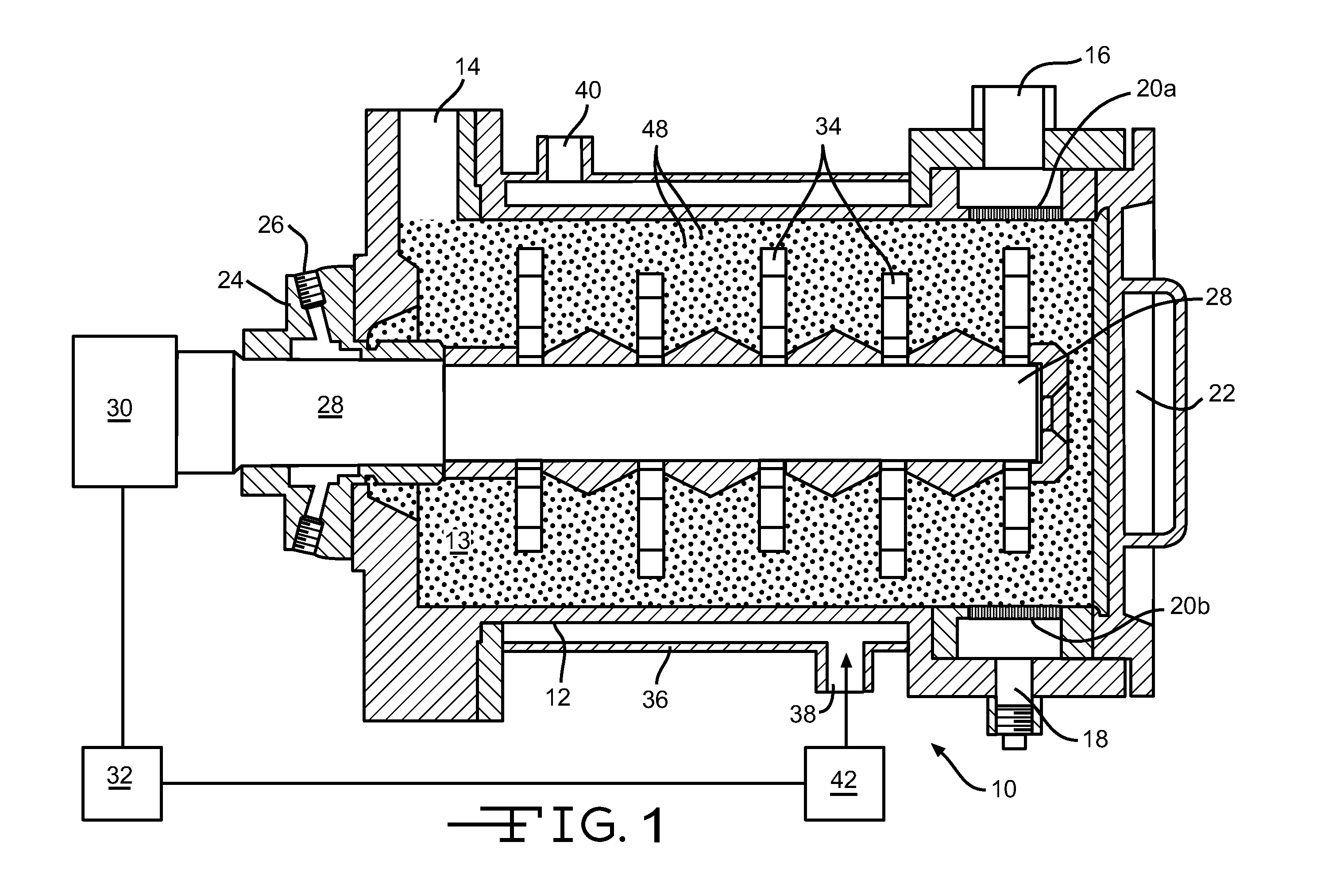
Image

Examples
example 1
[0112]Table 1 sets forth a list of components that may be used to make at least one exemplary embodiment of the inventive foam.
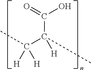
TABLE 1List of Foam Composition Ingredient OptionsTrade NameDescriptionManufacturerFunctionalized LatexOmnapel 6110Carboxylated Acrylic LatexOmnova Solutions,Inc.NovaCryl PSP 170Carboxylated Acrylic LatexOmnova Solutions,Inc.GenFloCarboxylated SBR LatexOmnova Solutions,Inc.Non-Functionalized LatexAcryGen DV300Acrylic LatexOmnova Solutions,Inc.Vycar 660x144Acrylic LatexNoveonF-6694SBR LatexOmnova Solutions,Inc.Crosslinking AgentsXAMA 7Multifunctional AziridineBayer ChemicalLindride 56MethylhexahydrophthalicLindau ChemicalAnhydrideHardner CDCarbodiimideRotta Corp.YDH 184Cycloaliphatic DiepoxideThai EpoxyBlowing Agent (Base / Acid pairs)Sodium Bicarbonate / CitricAldrichAcidSodium Carbonate / CitricAldrichAcidCalcium Carbonate / SodiumAldrichBicarbonate / Citric AcidSodium Bicarbonate / Poly-Solvay / Rohm&Haasacrylic AcidPotassium Bicarbonate / Poly-acrylic acidSurfactantG-5M ...
example 2
Determination of Air Leakage
[0118]Various wall structures were tested for air leakage according to the standards set forth in ASTM E283, which is hereby incorporated herein by reference in its entirety. The framed structures were formed of conventional framing studs spaced 16 inches apart externally walled with sheathing formed of oriented strand boards, similar to that illustrated in FIG. 2. The various iterations of the sample wall structures and air leakage results for each are set forth in Table 5.
TABLE 5Air LeakageAir LeakageWall StructureSCFM @ 75 PaNo Inventive Foam UtilizedWall without sealant, no seams taped37.1aWall without sealant, seam taped37.1aWall without sealant, seam taped, window37.1acoveredWall insulated and drywalled26.5Wall Sealed with Inventive FoamWall sealed with inventive foam and window8.4frame foamedWall sealed with inventive foam, insulation8.9positioned in cavity, and drywall affixed tostudsWall sealed with inventive foam and scraped9.4off surface, no in...
example 3
Rate of Rise of Foam Containing Sodium Bicarbonate
[0120]A foam according to the present invention was prepared according to the procedure set forth above. In particular, a first component containing a functionalized resin (i.e., a carboxylated acrylic latex) and an acid (i.e., polyacrylic acid) and a second component containing a room temperature crosslinking agent (i.e., a polyfunctional aziridine) and sodium bicarbonate were mixed and the components were permitted to react to form a foam. The foam was permitted to rise to a 700 ml expansion. In one sample, the sodium bicarbonate had a mean particle size of 50 microns. In the second sample, the sodium bicarbonate had a mean particle size of 11 microns. The results are set forth in Table 6.
TABLE 6Rate of Rise Due To Sodium BicarbonateSize of Sodium Bicarbonate (microns)Time (seconds)11285050
PUM
| Property | Measurement | Unit |
|---|---|---|
| Length | aaaaa | aaaaa |
| Length | aaaaa | aaaaa |
| Particle size | aaaaa | aaaaa |
Abstract
Description
Claims
Application Information