Dielectric deposition using a remote plasma source

a plasma source and dielectric technology, applied in the field of sputter deposition process tools, can solve the problems of poor heat conductivity of dielectric materials, limited deposition rate of dielectric materials in conventional radio frequency sputtering, and non-uniform power density, so as to achieve uniform argon ion distribution, reduce thermal stress, and increase power density

Inactive Publication Date: 2011-09-22
APPLIED MATERIALS INC
View PDF19 Cites 36 Cited by
  • Summary
  • Abstract
  • Description
  • Claims
  • Application Information

AI Technical Summary

Benefits of technology

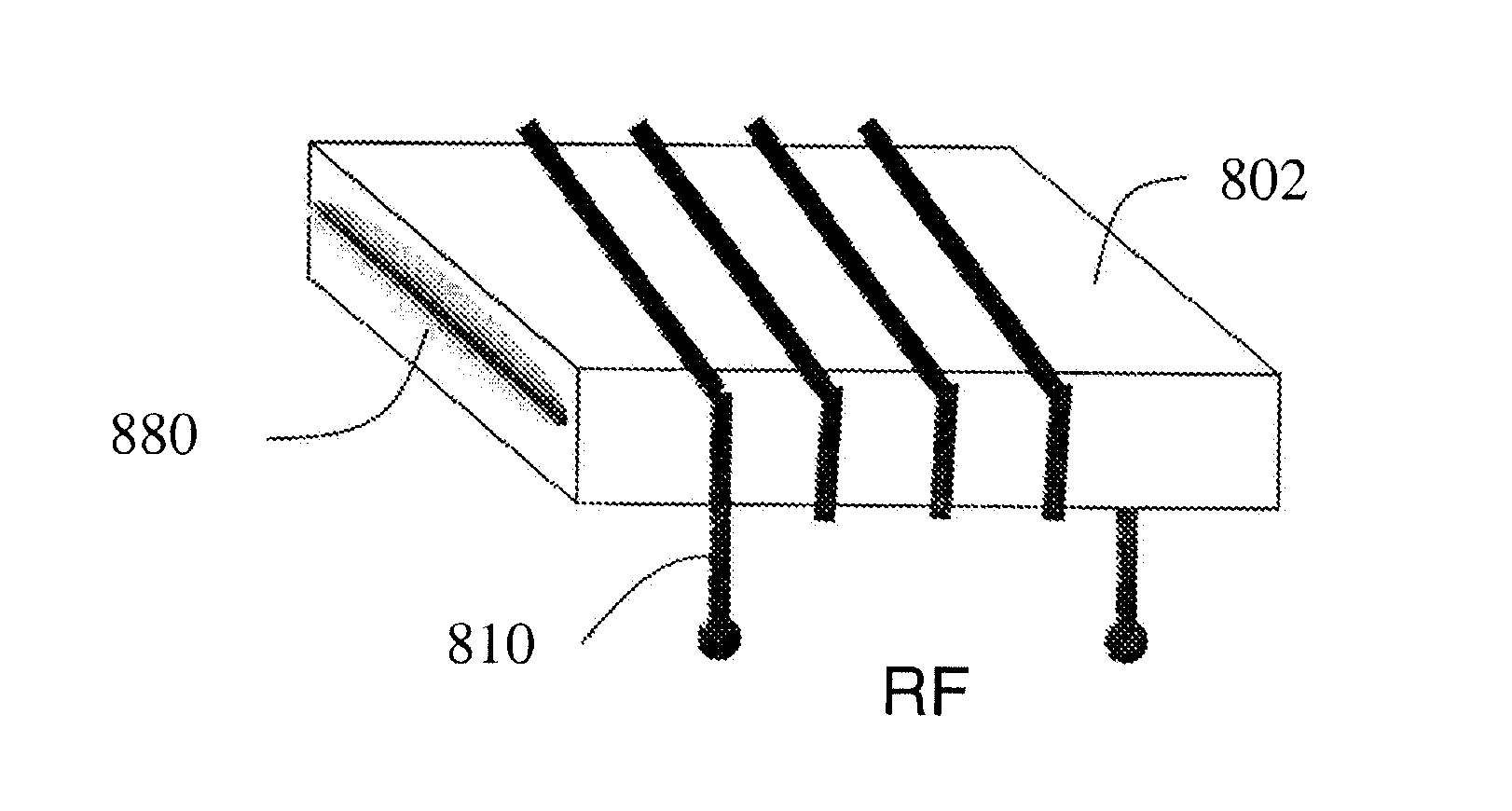
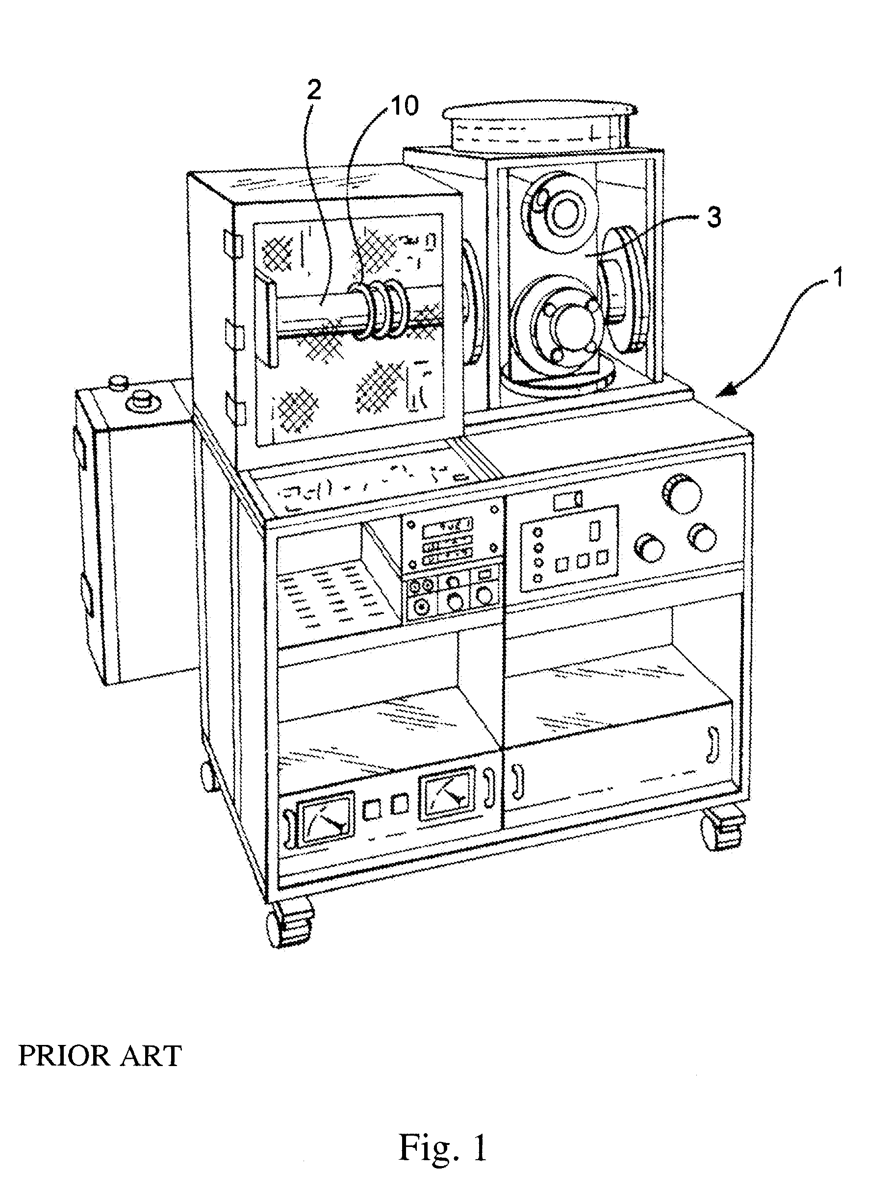
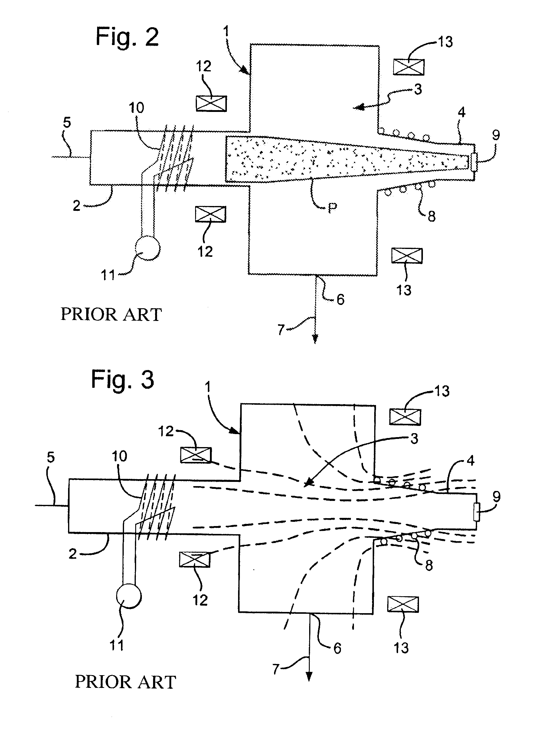
[0005]Embodiments of the present invention provide sputter deposition tools and methods that provide manufacturing advantages for UPON deposition for thin film batteries using Li3PO4 (lithium orthophosphate) sputtering targets. By using a remote plasma source, such as offered by Plasma Quest Ltd, U.K. and described in U.S. Pat. Nos. 6,463,873 and 7,578,908 and at www.plasmaquest.com.uk (last visited on Mar. 19, 2010), a more uniform argon ion distribution across the Li3PO4 target can be achieved. This results in more even heating of the Li3PO4 target, resulting in reduced thermal stress. Thus the power density can be increased, resulting in higher LiPON deposition rates.

Problems solved by technology

Deposition rates in conventional radio frequency (RF) sputtering of dielectric materials are limited by the power density that can be applied to the target before the material cracks due to internal thermal stresses.
Dielectric materials are usually poor heat conductors.
This results in a non-uniform power density across the target, causing uneven heating of the target, build-up of internal stresses and even cracking in the target.
In particular, dielectric targets used for sputter depositing lithium phosphorus oxynitride (LiPON) electrolyte material in the fabrication of thin film batteries are susceptible to cracking.

Method used


Image

  • Dielectric deposition using a remote plasma source
  • Dielectric deposition using a remote plasma source
  • Dielectric deposition using a remote plasma source

Examples


Embodiment Construction

[0022]Embodiments of the present invention will now be described in detail with reference to the drawings, which are provided as illustrative examples of the invention so as to enable those skilled in the art to practice the invention. Notably, the figures and examples below are not meant to limit the scope of the present invention to a single embodiment, but other embodiments are possible by way of interchange of some or all of the described or illustrated elements. Moreover, where certain elements of the present invention can be partially or fully implemented using known components, only those portions of such known components that are necessary for an understanding of the present invention will be described, and detailed descriptions of other portions of such known components will be omitted so as not to obscure the invention. In the present specification, an embodiment showing a singular component should not be considered limiting; rather, the invention is intended to encompass ...


PUM

PropertyMeasurementUnit
diameteraaaaaaaaaa
diameteraaaaaaaaaa
sizeaaaaaaaaaa

Abstract

A sputter deposition system comprises a vacuum chamber including a vacuum pump for maintaining a vacuum in the vacuum chamber, a gas inlet for supplying process gases to the vacuum chamber, a sputter target and a substrate holder within the vacuum chamber, and a plasma source attached to the vacuum chamber and positioned remotely from the sputter target, the plasma source being configured to form a high density plasma beam extending into the vacuum chamber. The plasma source may include a rectangular cross-section source chamber, an electromagnet, and a radio frequency coil, wherein the rectangular cross-section source chamber and the radio frequency coil are configured to give the high density plasma beam an elongated ovate cross-section. Furthermore, the surface of the sputter target may be configured in a non-planar form to provide uniform plasma energy deposition into the target and/or uniform sputter deposition at the surface of a substrate on the substrate holder. The sputter deposition system may include a plasma spreading system for reshaping the high density plasma beam for complete and uniform coverage of the sputter target.

Description

CROSS-REFERENCE TO RELATED APPLICATIONS[0001]This application claims the benefit of U.S. Provisional Application Ser. No. 61 / 316,306 filed Mar. 22, 2010, incorporated by reference in its entirety herein.FIELD OF THE INVENTION[0002]The present invention relates generally to sputter deposition process tools, and more particularly to high productivity sputter deposition systems for dielectric materials configured with a plasma source remote from the sputter target.BACKGROUND OF THE INVENTION[0003]Deposition rates in conventional radio frequency (RF) sputtering of dielectric materials are limited by the power density that can be applied to the target before the material cracks due to internal thermal stresses. Dielectric materials are usually poor heat conductors. The magnetron in conventional sputtering sources confines the Ar plasma in a racetrack pattern. This results in a non-uniform power density across the target, causing uneven heating of the target, build-up of internal stresses...

Claims


Application Information

Patent Timeline
Patent Type & Authority Applications(United States)
IPC IPC(8): C23C14/34C23C14/35C23C14/06C23C14/46
CPCC23C14/06C23C14/3407C23C14/354H05H2001/4667H01J37/34C23C14/0036H05H1/46H01J37/32357H05H1/4652
Inventor HOFMANN, RALFFOAD, MAJEED A.
Owner APPLIED MATERIALS INC
Why Eureka
Try Eureka