Coal conversion process and products, comprising two direct ebullated bed liquefaction stages and a fixed bed hydrocracking stage

a technology of hydrocracking and coal conversion process, which is applied in the direction of hydrocarbon oil treatment products, waste based fuels, fuels, etc., can solve the problems of poor quality and more astonishing, and achieve the effect of high yield

Active Publication Date: 2011-09-22
INST FR DU PETROLE
View PDF7 Cites 34 Cited by
  • Summary
  • Abstract
  • Description
  • Claims
  • Application Information

AI Technical Summary

Benefits of technology

[0013]The goal of the industrial development of direct coal liquefaction is to obtain fuel bases in a high yield and with qualities which are acceptable having regard to the final specifications and / or restrictions imposed by the subsequent transformation stages.

Problems solved by technology

These results are all the more astonishing since fuel bases produced by direct coal liquefaction are conventionally known to be of poor quality failing to comply with specifications regarding combustion because of their high naphtheno-aromatics content.

Method used


Image

  • Coal conversion process and products, comprising two direct ebullated bed liquefaction stages and a fixed bed hydrocracking stage
  • Coal conversion process and products, comprising two direct ebullated bed liquefaction stages and a fixed bed hydrocracking stage
  • Coal conversion process and products, comprising two direct ebullated bed liquefaction stages and a fixed bed hydrocracking stage

Examples


example 1

Liquefaction Stages

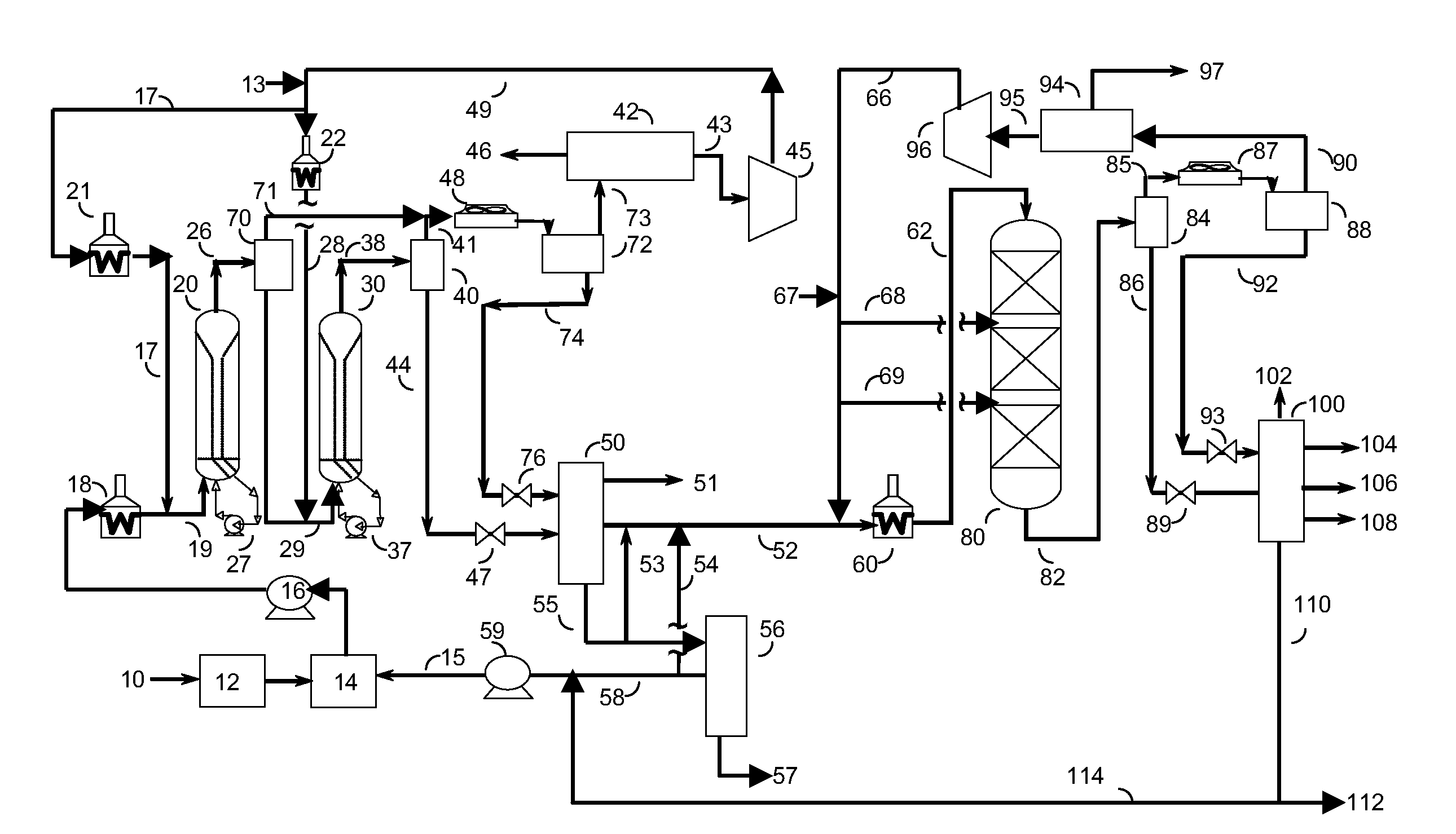
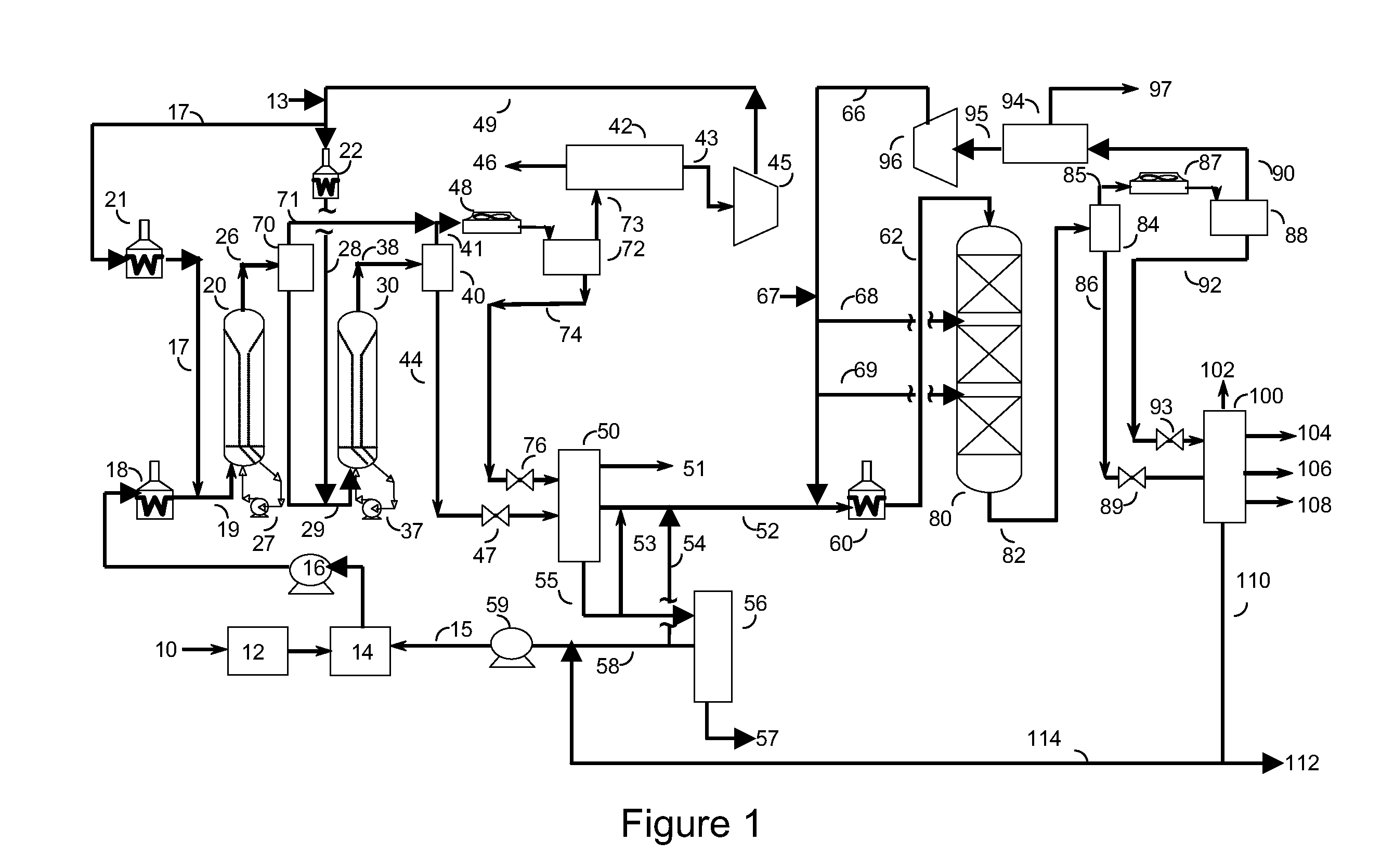
[0186]The two liquefaction stages in ebullated bed reactors were carried out with bituminous type coal which had been ground and dried. The operating conditions for the liquefaction are shown in Table 1; the liquefaction yields are shown in Table 2.

TABLE 1operating conditions for two-stage liquefactionCatalystNiMo / aluminaTemperature, reactor R1 (° C.)410Temperature, reactor R2 (° C.)440Pressure, MPa17HSV R1 (kg / h dry coal / kg catalyst)1.2HSV R2 (kg / h dry coal / kg catalyst)1.2H2 inlet (Nm3 / kg dry coal)2.8Recycle, liquid / coal1.1

TABLE 2yields for two-stage liquefaction (wt % / dry coal)C1-C4 (gas)13.53C5-199° C.14.00199-260° C.9.79260-343° C.21.52343-388° C.13.54388-454° C.4.04454-523° C.1.20523° C.+2.41Unconverted coal + ash13.23H2O / CO / CO2 / NH3 / H2S13.80

example 2

Hydrocracking Stage

[0187]The C5-199° C., 199-260° C., 260-343° C. and 343-388° C. cuts obtained in the separation stage at the liquefaction outlet were sent to the hydrocracking stage. The portion of the heavy fraction which was not recycled, the unconverted coal and the ash were sent to the gasification stage in order to produce H2. The operating conditions for hydrocracking are shown in Table 3; the hydrocracking yields are shown in Table 4.

TABLE 3operating conditions for hydrocrackingCatalystNiW / silica-aluminaPressure, MPa16Temperature (° C.)390HSV (Nm3 / h C5-388° C. / m3 of catalyst)0.5H2 / HC, reactor inlet (Nm3 / h H2 / Nm3 C5-388° C.)1500

TABLE 4yields for hydrocracking (wt % / dry coal)H2S / NH3 / H2O1.0C1-C40.81C5-200° C.19.16200-250° C.11.83250° C.+27.73200° C.+39.56343° C.+4.02

[0188]Table 5 shows the physico-chemical properties of the 200° C.+ cut of the hydrocracked coal from liquefaction as well as the properties of the kerosene cut and the gas oil cut obtained by distillation of this ...

example 3

Hydrotreatment Stage (Not in Accordance With the Invention)

[0191]In order to explain the hydrotreatment effect on the liquefaction effluent, a complementary test was carried out by hydrotreating the C5-199° C., 199-260° C., 260-343° C. and 343-388° C. cuts obtained in the separation stage at the liquefaction outlet of Example 1. The operating conditions for the fixed bed hydrotreatment are shown in Table 7.

TABLE 7operating conditions for hydrotreatmentCatalystNiMo / aluminaPressure, MPa13Temperature (° C.)375HSV (Nm3 / h C5-388° C. / m3 of catalyst)0.75H2 / HC (Nm3 / h H2 / Nm3 C5-388° C.)300

[0192]The ASTM D 3238 analyses were carried out on the 200-350° C. (kerosene+diesel) cuts obtained using the H-Coal TS process under the conditions of Example 1, obtained after hydrocracking (HCK) under the conditions of Example 2 and after hydrotreatment (HDT) under the conditions of Example 3. These analyses as shown in Table 8.

TABLE 8change in structure of 200-350° C. cut as function of treatmentUsing H-...


PUM

PropertyMeasurementUnit
temperatureaaaaaaaaaa
total pressureaaaaaaaaaa

Abstract

A process for the conversion of coal into fuel bases comprises two successive direct liquefaction stages in ebullated bed reactors followed by a fixed bed hydrocracking stage. This process can produce excellent quality fuel bases (kerosene and diesel).

Description

[0001]The present invention relates to a process for the conversion of coal, comprising two successive direct liquefaction stages in ebullated bed reactors followed by a fractionation and a fixed bed hydrocracking stage. This process is for the production of fuel bases, especially kerosene and gas oil, of very high quality.[0002]Coal liquefaction, better known by the term “coal-to-liquids”, or CTL, consists of converting coal into liquid hydrocarbons such as fuels or petrochemicals products. Coal liquefaction is based on two differently designed routes:[0003]The “indirect” route, based on BASF's 1913 patent and the work of the chemists Fischer and Tropsch in 1922, consists in a first stage of gasifying coal to a gas composed of carbon monoxide and hydrogen known as synthesis gas or “syngas”. This gas is then converted into liquid hydrocarbons by the Fischer-Tropsch process, using iron catalysts. That process means that conventional coals of the bituminous or sub-bituminous type can ...

Claims


Application Information

Patent Timeline
Patent Type & Authority Applications(United States)
IPC IPC(8): C10G1/00C10G1/06C10L1/04C10G1/10
CPCC10G1/002C10G2400/08C10G1/065C10L1/04C10L1/08Y02E50/32C10G2300/4018C10G2300/1003C10G2300/1014C10G2300/1018C10G2300/1033C10G2300/107C10G2300/1074C10G2300/1077C10G2300/301C10G2300/307C10G2300/308C10G2300/44C10G2400/02C10G2400/04C10G1/042Y02E50/30Y02P30/20
Inventor CHARON, NADEGEDULOT, HUGUESQUIGNARD, ALAINWEISS, WILFRIED
Owner INST FR DU PETROLE
Why Eureka
Try Eureka