

Method for processing wafer
a technology of wafers and processing methods, applied in the field of processing methods, can solve the problems of lowering the reliability and yield of the chip, the difficulty of individually peeled protection tapes, and the inability to use dicing, etc., and achieve the effect of facilitating the chip to be peeled
- Summary
- Abstract
- Description
- Claims
- Application Information
AI Technical Summary
Benefits of technology
Problems solved by technology
Method used
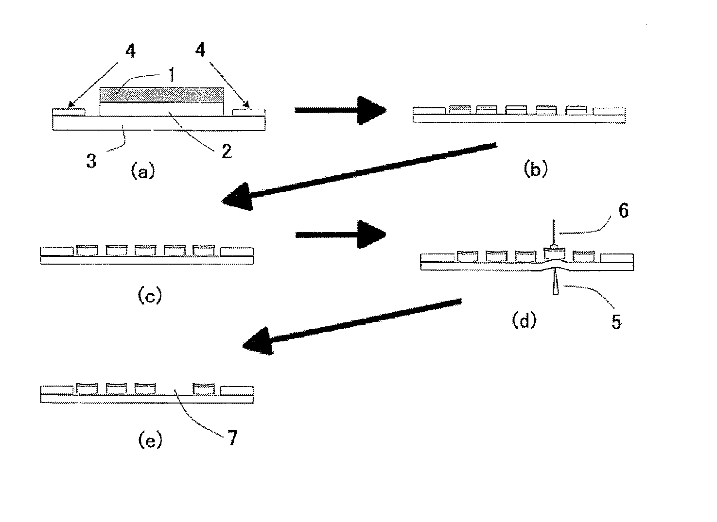
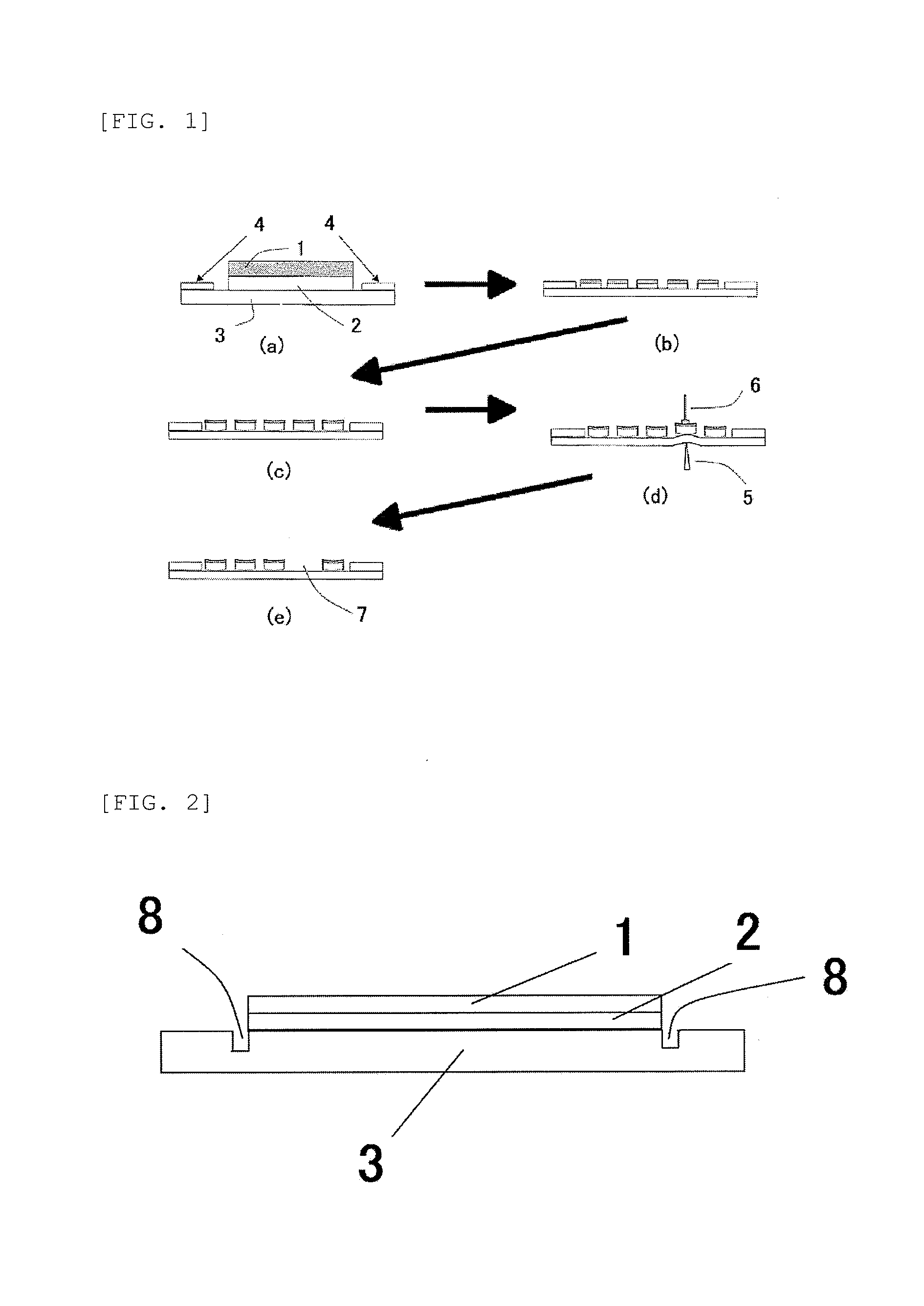
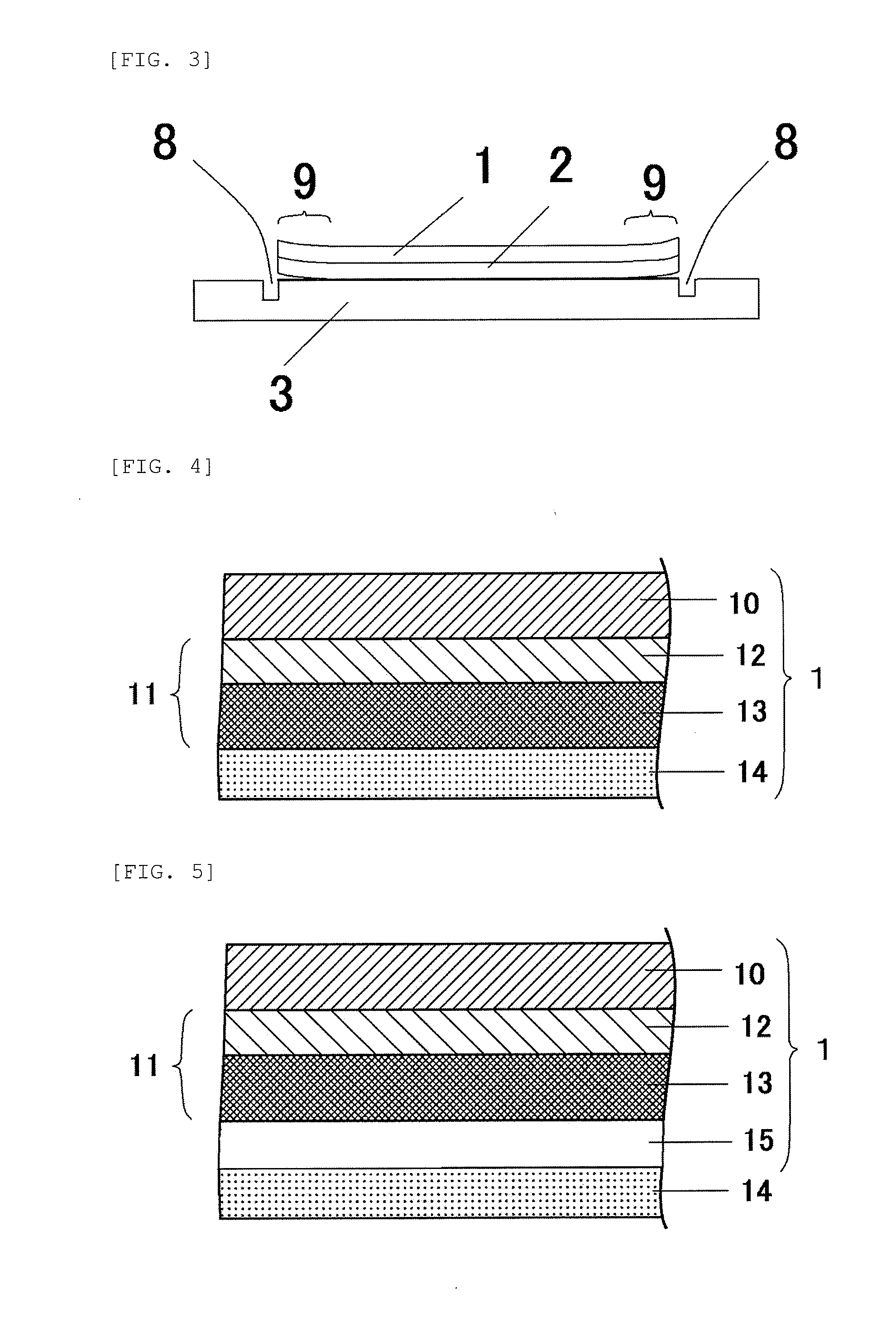
Image

Examples
manufacture example 1
Manufacture of Active Energy Beam Curing Type Tackiness Agent Layer (1)
[0257]An acrylic polymer having a methacrylate group in the side chain was produced by combining 50% of hydroxyl groups originating in 2-hydroxyethyl acrylate of an acrylic polymer [which was produced by copolymerizing a composition: 2-ethylhexyl acrylate:morpholyl acrylate:2-hydroxyethyl acrylate=75:25:22 (molar ratio)] with methacryloyloxyethyl isocyanate (2-isocyanato ethyl methacrylate).
[0258]An active energy beam curing type tackiness agent was prepared by mixing 15 parts by weight of ARONIX M320 (made by Toagosei Co., Ltd.; trimethylol-propane-PO-denaturated (n≠2) triacrylate), which is a photopolymerizable crosslinking agent, one part by weight of a photoinitiator (made by Ciba-Geigy Corporation, trade name “IRGACURE 651”), and one part by weight of an isocyanate crosslinking agent (trade name “CORONATE L”), with respect to 100 parts by weight of the acrylic polymer having the methacrylate group in the sid...
manufacture example 2
Manufacture of Non-Active Energy Beam Curing Type Tackiness Agent Layer (1)
[0260]A non-active energy beam curing type tackiness agent was prepared by mixing 0.7 parts by weight of an epoxy-based crosslinking agent (made by MITSUBISHI GAS CHEMICAL COMPANY, INC., trade name “TETRAD C”) and 2 parts by weight of an isocyanate-based crosslinking agent (trade name “CORONATE L”) with 100 parts by weight of an acrylic copolymer [which has been produced by copolymerizing a mixture of butyl acrylate:acrylic acid=100:3 (weight ratio)].
[0261]A laminated body in which the non-active energy beam curing type tackiness agent layer with a thickness of 30 μm was provided on the release sheet was obtained by coating the obtained non-active energy beam curing type tackiness agent on the release sheet (made by Mitsubishi Polyester Film Corporation, trade name “MRF38”) with the use of an applicator, and then by drying a volatile matter such as a solvent.
manufacture example 3
Manufacture of Active Energy Beam Curing Type Tackiness Agent Layer (2)
[0262]An acrylic polymer having a methacrylate group in the side chain was produced by combining 80% of hydroxyl groups originating in 2-hydroxyethyl acrylate of an acrylic polymer [which was produced by copolymerizing a composition: butyl acrylate:ethyl acrylate:2-hydroxyethyl acrylate=50:50:20 (molar ratio)] with methacryloyloxyethyl isocyanate (2-isocyanato ethyl methacrylate).
[0263]An active energy beam curing type tackiness agent was prepared by mixing 100 parts by weight of a compound with a trade name of “Shikoh UV1700” made by The Nippon Synthetic Chemical Industry Co., Ltd., as a compound containing two or more functional groups having a carbon-carbon double bond, 3 parts by weight of a photoinitiator (made by Ciba-Geigy Corporation, trade name “IRGACURE 184”) and 1.5 parts by weight of an isocyanate crosslinking agent (trade name “CORONATE L”) with respect to 100 parts by weight of the acrylic polymer h...
PUM
 Abstract
Description
Claims
Application Information