High power vcsel with improved spatial mode

a technology of spatial mode and high power, which is applied in the direction of laser details, optical resonator shape and construction, printing, etc., can solve the problems of large-scale vcsels, which suffer from emission in higher-order spatial modes, are not very practical, and the complexity of the system is significantly increased, so as to achieve satisfying mode distribution and stability, and high power vcsel

Inactive Publication Date: 2011-10-06
KONINKLIJKE PHILIPS ELECTRONICS NV
View PDF4 Cites 10 Cited by
  • Summary
  • Abstract
  • Description
  • Claims
  • Application Information

AI Technical Summary

Benefits of technology

An object of the present invention is to provide a high power VCSEL device which emits laser radiation with satisfying mode distribution and stability at even higher power levels.

Problems solved by technology

These large scale VCSELs, however, suffer from emission in higher order spatial modes and in addition from a strong dependency of the spatial mode distribution on the feeding current in the device.
Additionally the strong dependence of the laser mode on the current allows only very selected operating points to maintain a stable emission mode and is therefore not very practical.
With this reduction of the reflectivity of the intermediate DBR to a value at which the laser does not operate without external optical feedback, the complexity of the system is significantly increased as the additional external mirror has to be aligned with very high precision.
A characterization of the system on wafer level is not possible for these reasons.
The use of a VECSEL instead of a VCSEL therefore adds complexity to the production process.
The very small tolerances in the alignment of the external mirror with respect to the semiconductor device require a sophisticated alignment and production process of single VECSEL diodes and an even more complicated and therefore more expensive alignment process when forming arrays of VECSEL diodes.

Method used


Image

  • High power vcsel with improved spatial mode
  • High power vcsel with improved spatial mode
  • High power vcsel with improved spatial mode

Examples


Embodiment Construction

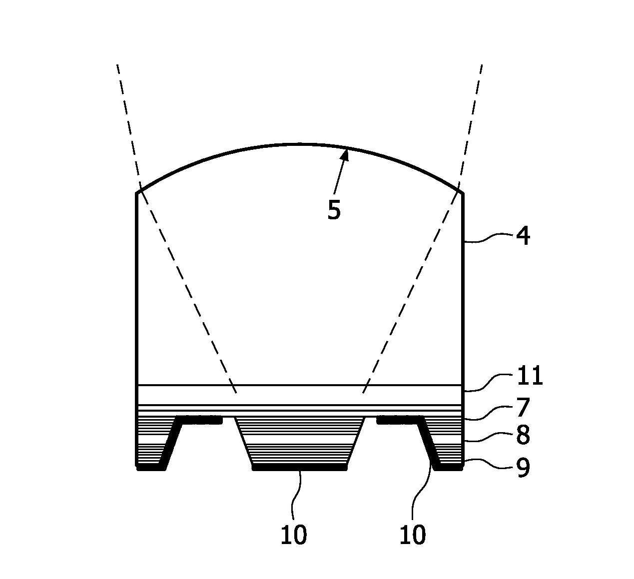
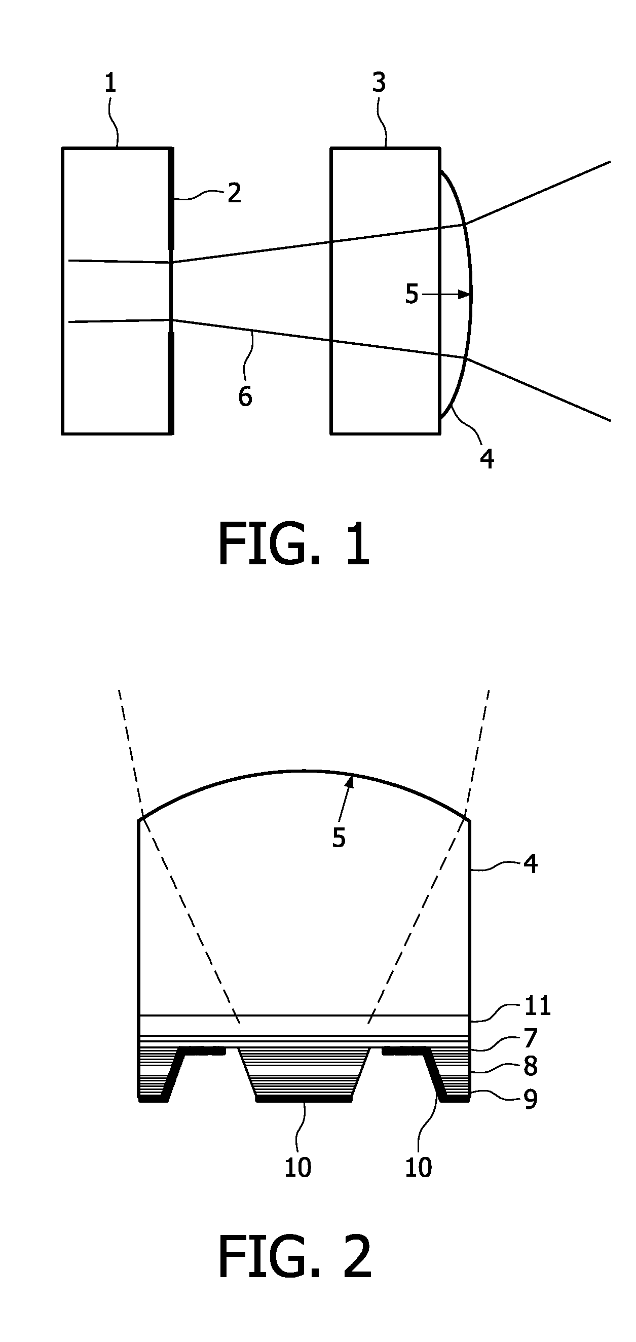
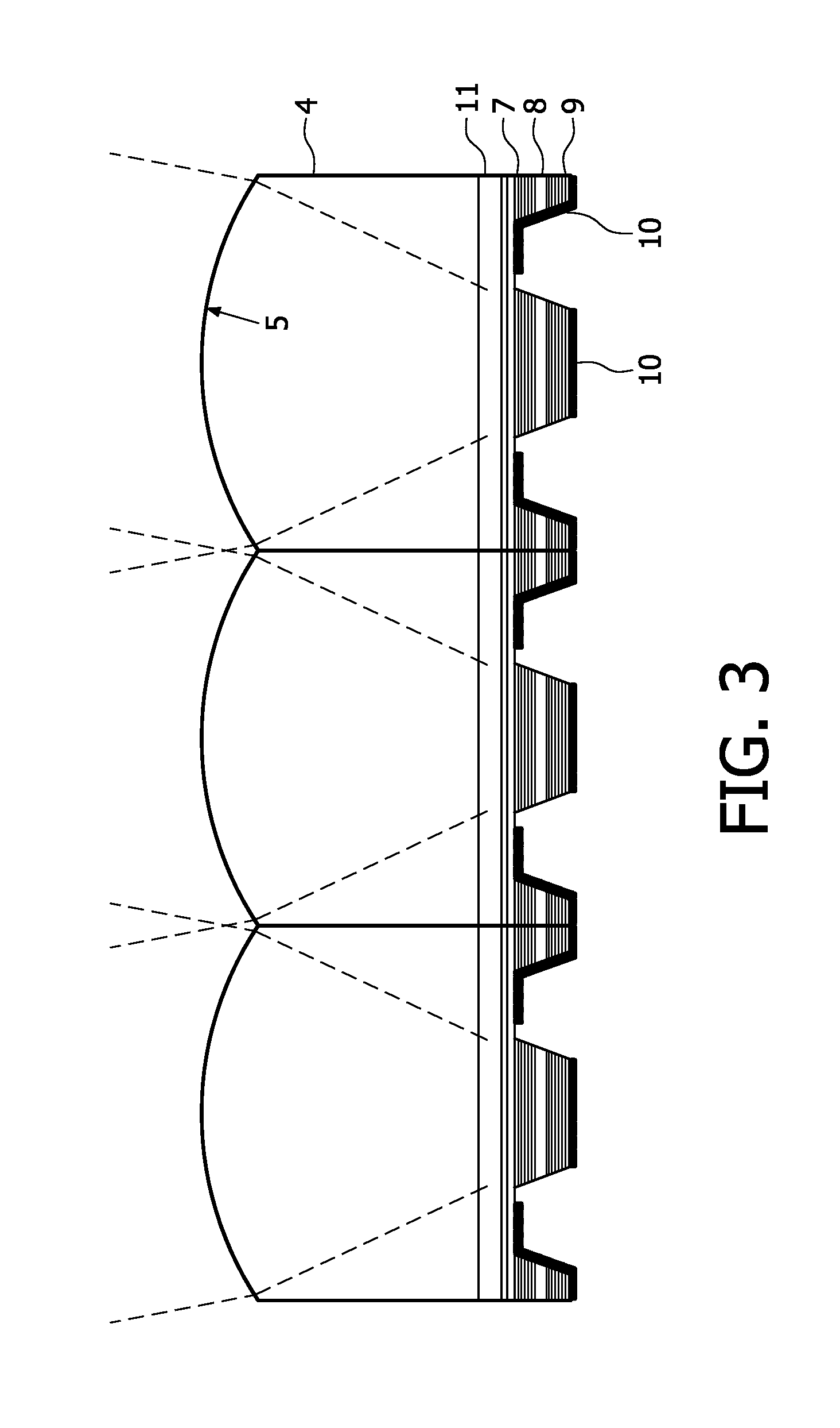
FIG. 1 shows a schematic view of a first example of the proposed VCSEL device. In this embodiment the weak feedback is realized by a curved mirror placed apart from the VCSEL 1, which is only indicated schematically in FIG. 1. A confinement layer 2 on the upper DBR of VCSEL 1 forms an aperture for the emitted laser radiation, the laser beam 6 being indicated in the figure. The optical element forming the reflecting surface for feedback is a coated micro lens 4 in this example. The coating may be a stack of appropriate dielectric layers like Ta2O5 and SiO2 or similar materials. This micro lens 4 is attached to a glass block 3 having a thickness of 200 μm. The air gap between the VCSEL 1 and this glass block 3 is 3 mm. The micro lens is coated to have a reflectivity of the inner surface 5 of 30% for the laser radiation, such that 30% of the laser radiation emitted by the VCSEL 1 is fed back into the laser cavity. This improves and stabilizes the spatial mode profile inside of the VCSE...


PUM


Abstract

The present invention relates to a VCSEL device comprising an optical gain medium (8) arranged between a first DBR (9) and a second DBR (7). The first and the second DBR form a laser cavity and are designed to allow self-contained lasing in the laser cavity, said second DBR (7) being partially transparent for laser radiation resonating in the laser cavity. An optical element is arranged on a side of the second DBR (7) outside of the laser cavity on the optical axis of the laser cavity. The optical element has a concave surface (5) facing the second DBR (7) and being designed to reflect a portion of laser radiation emitted through the second DBR (7) back into the laser cavity. The ratio R/d of the radius of curvature R of the concave surface (5) and the distance d between the concave surface (5) and the gain medium (8) is in the range between 1 and 2. With the proposed VCSEL device a high power output with an improved mode distribution and mode stabilization is achieved.

Description

FIELD OF THE INVENTIONThe present invention relates to a vertical cavity surface emitting laser (VCSEL) comprising an optical gain medium arranged between a first distributed Bragg reflector (DBR) and a second Distributed Bragg Reflector, said first and said second DBR forming a laser cavity and being designed to allow self-contained lasing in said laser cavity and said second DBR being partially transparent for laser radiation resonating in said laser cavity, and an optical element arranged on a side of said second DBR outside of said laser cavity on an optical axis of said laser cavity, said optical element having a concave surface facing said second DBR and being designed to reflect a portion of laser radiation passing through the second DBR back into the laser cavity.VCSEL devices emitting in the infrared wavelength range are quite common in optical communication applications. The laser cavity of such VCSEL devices consists of two stacks of distributed Bragg reflectors, which ar...

Claims


Application Information

Patent Timeline
Patent Type & Authority Applications(United States)
IPC IPC(8): H01S3/08
CPCB41J2/451H01S5/0207H01S5/423H01S5/18347H01S5/18388H01S5/0656
Inventor KOLB, JOHANNA S.MILLER, MICHAELWINTERSTEIN, SEBASTIENERNST, UWE
Owner KONINKLIJKE PHILIPS ELECTRONICS NV
Why Eureka
Try Eureka