Radiation imaging system and method

a technology of imaging system and imaging method, applied in imaging devices, instruments, applications, etc., can solve the problems of insufficient contrast of x-ray absorption contrast image of in vivo soft tissue, soft material, etc., and achieve the effect of improving the image quality of x-ray absorption contrast imag

Inactive Publication Date: 2011-10-06
FUJIFILM CORP
View PDF0 Cites 59 Cited by
  • Summary
  • Abstract
  • Description
  • Claims
  • Application Information

AI Technical Summary

Benefits of technology

[0014]An object of the present invention is to remove the effects of transmittance variation of diffraction gratings in a radiation imaging system that produces an X-ray absorption contrast image from a fringe image formed by X-rays having passed through the diffraction gratings.
[0031]According to the present invention, the radiation imaging system can capture both of the phase contrast image and the X-ray absorption contrast image at the same time. Before the production of the X-ray absorption contrast image, the individual characteristics of the radiation transmittance of the diffraction gratings are corrected for. As a result, the image quality of the X-ray absorption contrast image is improved.

Problems solved by technology

Thus, the X-ray absorption contrast image of in vivo soft tissue, soft material, or the like cannot have sufficient image contrast.
Thus, articular cartilage in the X-ray absorption contrast image of the arthrosis hardly has sufficient contrast with synovial fluid.
However, since the first and second diffraction gratings have fine structures with high aspect ratio, namely, the X-ray shield members and apertures are several μm in width and several tens of μm in thick in the direction of the X-ray path, it is very difficult to manufacture such gratings with sufficient accuracy.
The variation in the width and the thickness of the X-ray shield members and apertures causes a spatial variation in the X-ray transmittance of the diffraction gratings, and adverse effects on the image quality of the X-ray absorption contrast image.
However, this requires space and a mechanism to retract the first and second diffraction gratings, and results in increase in size and cost of the X-ray imaging system.
Also, it is difficult to precisely restore the first and second diffraction gratings from retraction positions into the X-ray path.

Method used


Image

  • Radiation imaging system and method
  • Radiation imaging system and method
  • Radiation imaging system and method

Examples


first embodiment

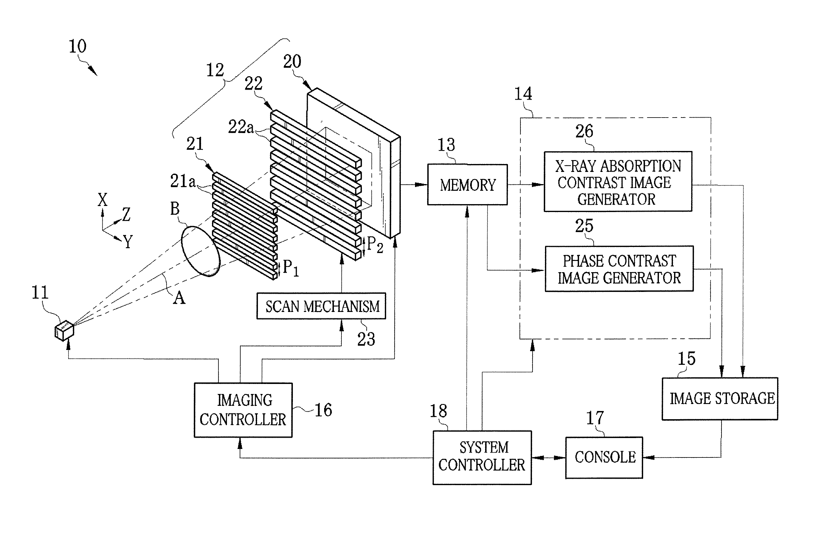
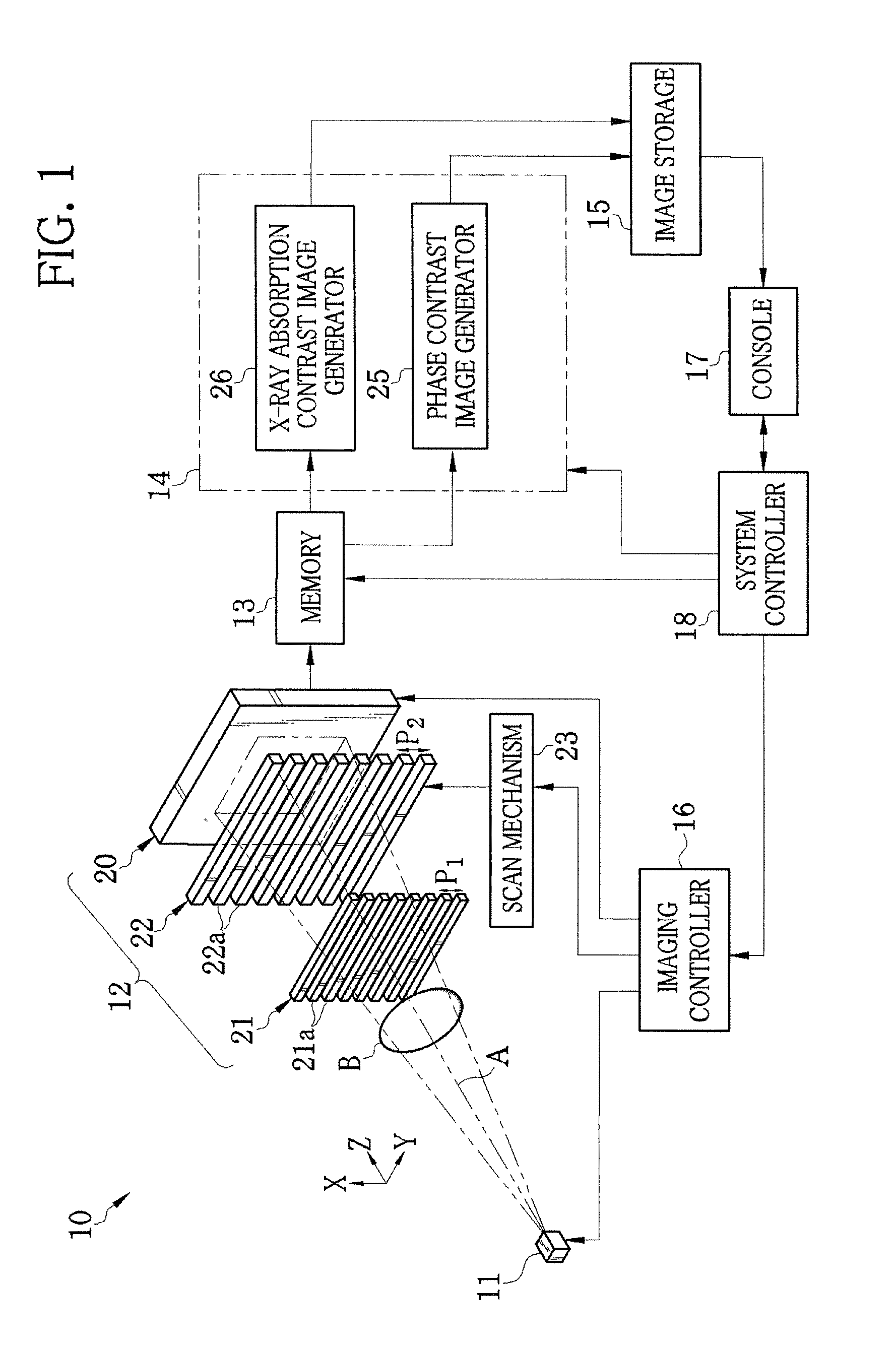
[0047]As shown in FIG. 1, an X-ray imaging system 10 according to a first embodiment is constituted of an X-ray source 11 for irradiating X-rays to an object B, an imaging unit 12 disposed so as to face the X-ray source 11, a memory 13, an image processor 14, an image storage 15, an imaging controller 16, a console 17 including an operation unit and a monitor, and a system controller 18. The imaging unit 12 detects the X-rays that have been emitted from the X-ray source 11 and passed through the object B, to produce image data. The memory 13 stores the image data outputted from the imaging unit 12. The image processor 14 produces a phase contrast image from plural frames of image data stored on the memory 13. The image storage 15 stores the phase contrast image produced by the image processor 14. The imaging controller 16 controls the X-ray source 11 and the imaging unit 12. The system controller 18 carries out centralized control of the entire X-ray imaging system 10 based on an op...

second embodiment

[0101]In the first embodiment, the second absorption grating 22 is provided separately from the FPD 20. However, the use of an X-ray image detector disclosed in U.S. Pat. No. 7,746,981 eliminates the provision of the second absorption grating 22. This X-ray image detector being a direct conversion X-ray image detector is provided with a conversion layer for converting the X-rays into electric charges and charge collection electrodes for collecting the electric charges converted by the conversion layer. In each pixel, the charge collection electrode includes plural linear electrodes arranged at a prescribed period. The plural linear electrodes are grouped and electrically connected to compose linear electrode groups. The linear electrode groups are laid out so as to be regularly out of phase with one another. The charge collection electrodes correspond to the intensity modulator.

[0102]FIG. 12 shows a FPD according to this embodiment. In the FPD, pixels 70 are arranged in two dimensio...

third embodiment

[0106]A small angle scattering image may be produced based on the plural images captured in the fringe scanning. To be more specific, as shown in FIG. 13, an image processor 81 according to a third embodiment is provided with the phase contrast image generator 25, the X-ray absorption contrast image generator 26, and a small angle scattering image generator 80. Any of the phase contrast image generator 25, the X-ray absorption contrast image generator 26, and the small angle scattering image generator 80 carries out arithmetic processing based on the image data obtained in each of the M number of scan positions of k=0, 1, 2, . . . , M−1. The phase contrast image generator 25 produces the phase contrast image, and the X-ray absorption contrast image generator 26 produces the X-ray absorption contrast image by the procedure described in the first embodiment.

[0107]As shown in FIG. 14, the small angle scattering image generator 80 calculates and images amplitude of the pixel data of eac...


PUM

PropertyMeasurementUnit
peak wavelengthaaaaaaaaaa
voltageaaaaaaaaaa
thicknessaaaaaaaaaa

Abstract

A radiation imaging system includes an X-ray source, first and second absorption gratins disposed in a path of X-rays emitted from the X-ray source, and an FPD. The second absorption grating is stepwise slid in an X direction relatively against the first absorption grating. Whenever the second absorption grating is slid, the FPD captures a fringe image and produces image data. A correction section corrects the image data for spatial variation of X-ray transmittance of the first and second absorption gratings. A phase contrast image generator produces a phase contrast image from the corrected image data. An X-ray absorption contrast image generator calculates a value related to an average of the corrected image data on a pixel-by-pixel basis, and produces an X-ray absorption contrast image from the value.

Description

BACKGROUND OF THE INVENTION[0001]1. Field of the Invention[0002]The present invention relates to a radiation imaging system and method that capture a phase contrast image of an object with the use of a diffraction grating.[0003]2. Description Related to the Prior Art[0004]X-rays are used as a probe for imaging inside of an object without incision, due to the characteristic that attenuation of the X-rays depends on the atomic number of an element constituting the object and its density and thickness. Radiography using the X-rays is widely available in fields of medical diagnosis, nondestructive inspection, and the like.[0005]In a conventional X-ray imaging system for capturing a radiographic image of the object, the object to be examined is disposed between an X-ray source for emitting the X-rays and an X-ray image detector for detecting the X-rays. The X-rays emitted from the X-ray source are attenuated (absorbed) in accordance with the characteristics (atomic number, density, and t...

Claims


Application Information

Patent Timeline
Patent Type & Authority Applications(United States)
IPC IPC(8): G01N23/04
CPCG01N23/04G21K1/025A61B6/484A61B6/582G21K2207/005G01N23/041
Inventor MURAKOSHI, DAI
Owner FUJIFILM CORP
Why Eureka
Try Eureka