
Fluorescent calcium indicators that are ratiometric and emit in the red spectrum

a technology of ratiometric and fluorescent indicators, applied in the field of long wavelength fluorescent ion indicators, can solve the problems of limited general use of ultraviolet light, high energy ultraviolet light can also be harmful to the cell, and high cost of ultraviolet ligh

Inactive Publication Date: 2011-10-20
MINTA AKWASI +1
View PDF2 Cites 4 Cited by
  • Summary
  • Abstract
  • Description
  • Claims
  • Application Information

AI Technical Summary

Benefits of technology

"The present invention introduces a new family of calcium indicators that can be used to measure intracellular calcium levels. These indicators have emissions in the red and near infrared regions of the electromagnetic spectrum. They are derived from a BAPTA or BAPTA-like backbone for calcium chelation, and the red or infrared fluorescence is achieved by linking the chelating portion with a chlorinated and fluorinated Benzo[c]xanthenone. The longer wavelength causes a slight reduction of quantum yield. Overall, these indicators provide a useful tool for studying calcium-related biological processes."

Problems solved by technology

UV optics are expensive and hence have limited the general use of these dyes.
The high energy UV light can also be harmful to the cell.
The intrinsic fluorescence due to nucleotides and some amino acids when exciting with UV light also causes interference during measurement, although ratiometry does attenuate this problem.
The first, BTCiii, has a very high dissociation constant Kd that does not allow for measurement of small changes in cytosolic concentrations (nanomolar) of calcium.
The second, Fura-Rediv, has a low quantum yield in water due to its hydrophobicity and therefore has not found much use in cellular studies.

Method used


Image

  • Fluorescent calcium indicators that are ratiometric and emit in the red spectrum
  • Fluorescent calcium indicators that are ratiometric and emit in the red spectrum
  • Fluorescent calcium indicators that are ratiometric and emit in the red spectrum

Examples


Embodiment Construction

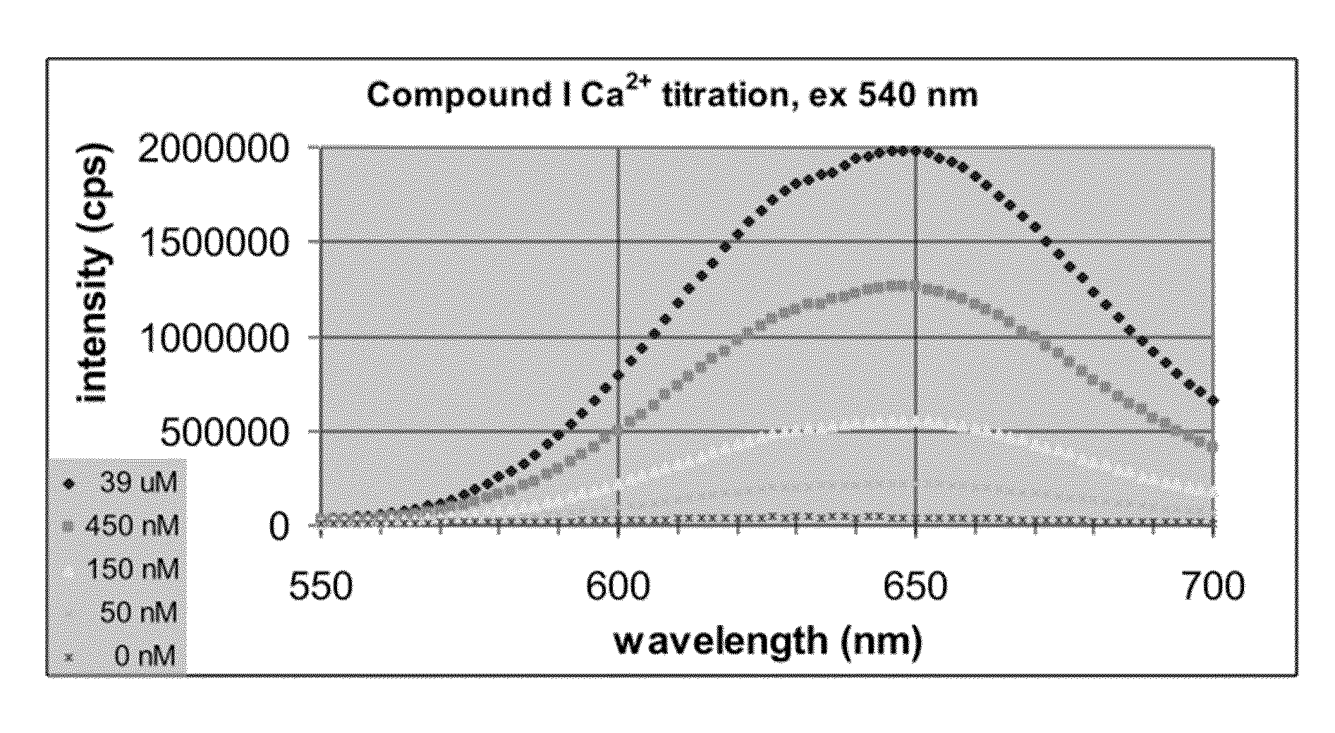
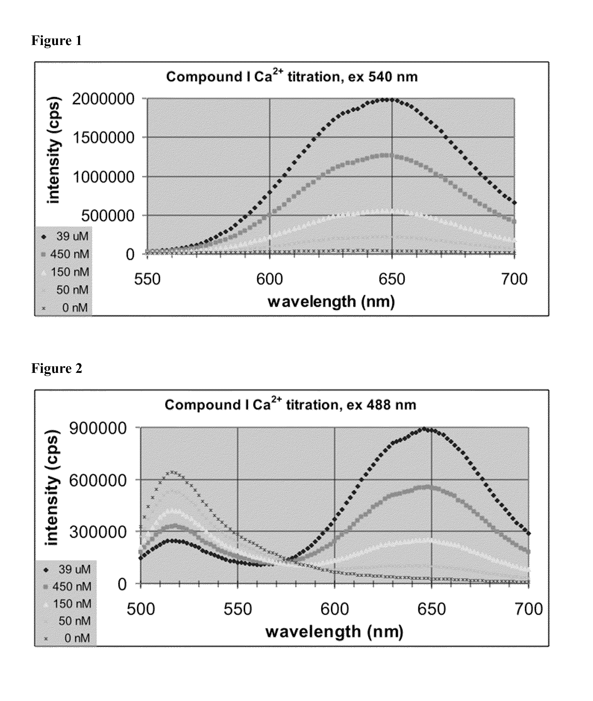
[0053]FIG. 1 shows a non-ratiometric calcium titration of Compound I. Appropriate volumes of 10 mM potassium-EGTA, 100 mM KCl, 10 mM MOPS buffer at pH 7.20 and 10 mM calcium-EGTA, 100 mM KCl, 10 mM MOPS buffer at pH 7.20, each containing 5 μM Compound I were mixed to give the desired free calcium concentrations of 0 nM, 50 nM, 150 nM, 450 nM, and 39 μM. Emission spectra were recorded of each solution with excitation at 540 nm, resulting in a strong increase in emission intensity at 650 nm with increasing calcium concentration. Calculation of dissociation constant gave approximately 400 nM. Spectra were recorded on SPEX Fluoromax-3.

[0054]FIG. 2 shows a ratiometric calcium titration of Compound I. Appropriate volumes of 10 mM potassium-EGTA, 100 mM KCl, 10 mM MOPS buffer at pH 7.20 and 10 mM calcium-EGTA, 100 mM KCl, 10 mM MOPS buffer at pH 7.20, each containing 5 μM Compound I were mixed to give the desired free calcium concentrations of 0 nM, 50 nM, 150 nM, 450 nM, and 39 μM. Emissi...


PUM

PropertyMeasurementUnit
pKaaaaaaaaaaa
pKaaaaaaaaaaa
dissociation constantsaaaaaaaaaa

Abstract

A new generation of fluorescent ion indicators for measuring cytosolic concentrations of calcium. These new indicators emit in the red portion of the visible spectrum and are ratiometric. The ratiometry consists of shifting in the emission upon binding calcium when exciting with an argon laser at 488 nm. These indicators also show marked increases in red fluorescence when excited with visible light at longer wavelengths. Like all calcium indicators, they comprise the usual chelating portion based on BAPTA (Bis Amino Phenyl Tetraacetic Acid) and a fluorophore portion, either a seminaphthofluorescein / seminaphthorhodamine or dinaphthofluorescein, which enable ratiometry. Unlike other naphthofluoresceins, the pKa has been adjusted on the naphtho moiety to make it suitable for biological calcium measurements. The invention relates to the structures of the indicators and to the method of synthesizing these indicators.

Description

RELATED APPLICATIONS[0001]This application is related to U.S. Provisional Patent Application No. 61 / 252,654 filed Oct. 17, 2010 by applicants, and claims the priority date of that application.BACKGROUND[0002]1. Field of Invention[0003]This application relates to the design and synthesis of long wavelength fluorescent ion indicators.[0004]2. Prior Art[0005]The most popular fluorescent calcium indicators that are ratiometric include Fura-2 (excitation shifting) and Indo-1 (emission shifting)i. Ratiometry has the unique advantage of eliminating the variable effects in calcium measurement such as indicator concentration, degree of cell loading, photobleaching, detector sensitivity, cell thickness, and optical path. It is essentially an ideal property that allows for calibration and quantitative measurements. However, these popular ratiometric dyes operate in ultraviolet light. UV optics are expensive and hence have limited the general use of these dyes. The high energy UV light can also...

Claims


Application Information

Patent Timeline
Patent Type & Authority Applications(United States)
IPC IPC(8): C07D405/12C07D311/78
CPCC07D311/02
Inventor MINTA, AKWASIESCAMILLA, PEDRO ROGELIO
Owner MINTA AKWASI
Learn More