
Fuel cell system and electronic device

a fuel cell and electronic device technology, applied in the direction of secondary battery servicing/maintenance, battery/fuel cell control arrangement, electrochemical generators, etc., can solve the problems of secondary battery itself deterioration, rapid deterioration, increase in charge/discharge current for nominal capacity, etc., to suppress fuel cell deterioration, suppress secondary battery deterioration

Active Publication Date: 2011-11-03
MURATA MFG CO LTD
View PDF7 Cites 5 Cited by
  • Summary
  • Abstract
  • Description
  • Claims
  • Application Information

AI Technical Summary

Benefits of technology

[0007]However, such a hybrid configuration using a secondary battery still has an issue which is deterioration of a secondary battery itself. Specifically, since a secondary battery used in the hybrid configuration is basically provided to temporarily store an output generated from a fuel cell, it is desirable that the secondary battery is as small as possible. However, when a secondary battery of small capacity is used, inevitably, the maximum charge / discharge current for the nominal capacity increases (that is, large current such as 2C or 3C is charged / discharged). Further, increase in the maximum charge / discharge current causes quick deterioration in the secondary battery, so that deterioration in the secondary battery is a large issue in a hybrid system.
[0012]In a fuel cell system and an electronic device according to an embodiment of the present invention, electromotive force generated by power generation of the power generation unit is stored in a secondary battery, and the fuel supply amount is adjusted so that the charging current to the secondary battery becomes smaller than a predetermined maximum charging current value. With the configuration, for example, even in the case where a small secondary battery is used and the charging current to the secondary battery increases, the charging current is limited to be smaller than a predetermined upper limit value (maximum charging current value). Further, the temperature of the secondary battery is detected and the maximum charging current value is controlled according to the detected temperature of the secondary battery, and thereby enabling the operation of limiting the charging current in accordance with the temperature at that time.

Problems solved by technology

However, such a hybrid configuration using a secondary battery still has an issue which is deterioration of a secondary battery itself.
However, when a secondary battery of small capacity is used, inevitably, the maximum charge / discharge current for the nominal capacity increases (that is, large current such as 2C or 3C is charged / discharged).
Further, increase in the maximum charge / discharge current causes quick deterioration in the secondary battery, so that deterioration in the secondary battery is a large issue in a hybrid system.
The cause of the deterioration phenomenon is that since the chemical reaction at the time of charging in the anode of the lithium ion battery (reaction of intercalation of the lithium ions between layers of carbon as an anode material) is slower than the charging speed, the lithium ion is deposited as metal lithium.
Further, since such intercalation reaction becomes slower as the temperature becomes lower, the deterioration phenomenon mentioned above becomes conspicuous particularly when the temperature is low.

Method used


Image

  • Fuel cell system and electronic device
  • Fuel cell system and electronic device
  • Fuel cell system and electronic device

Examples


embodiment

Example of General Configuration of Fuel Cell System

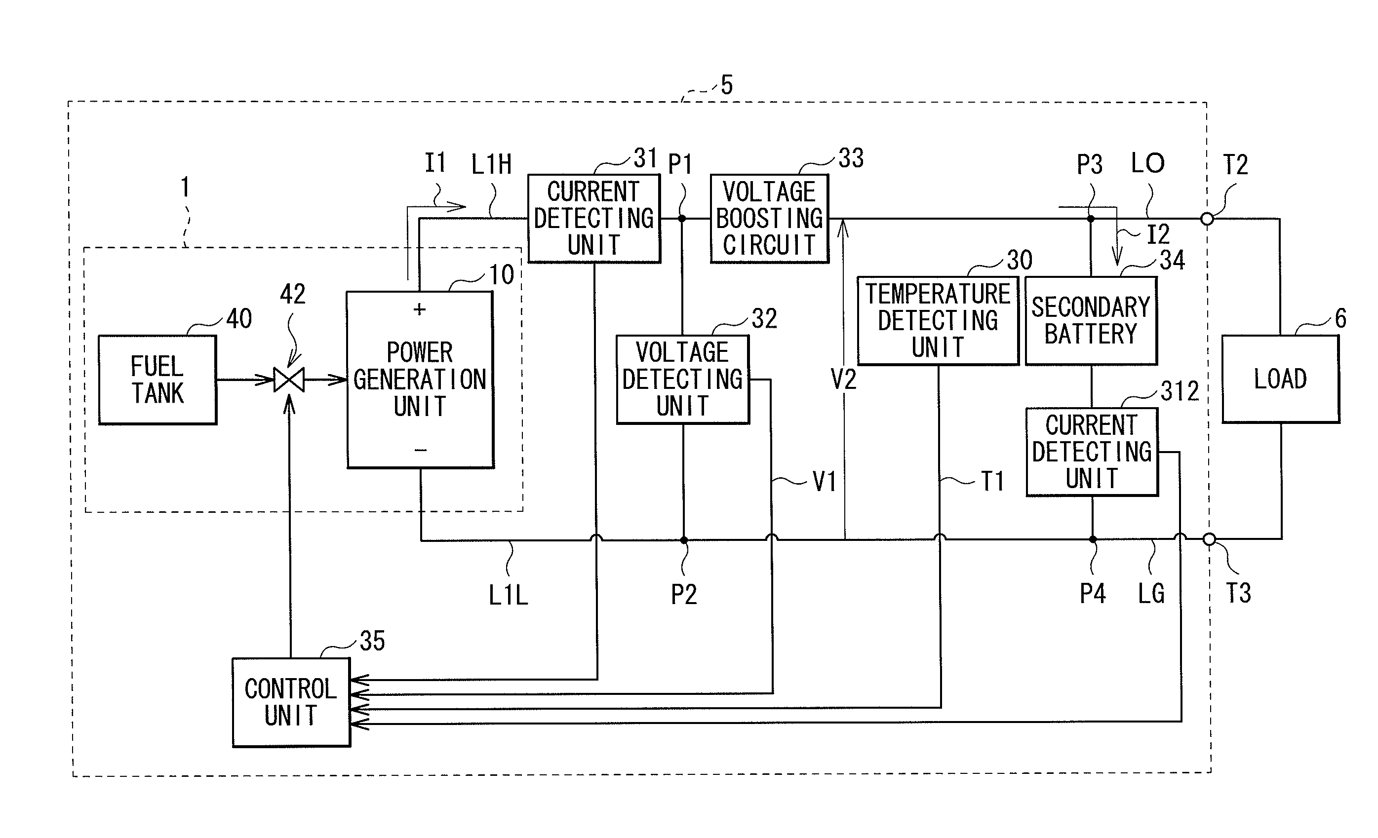
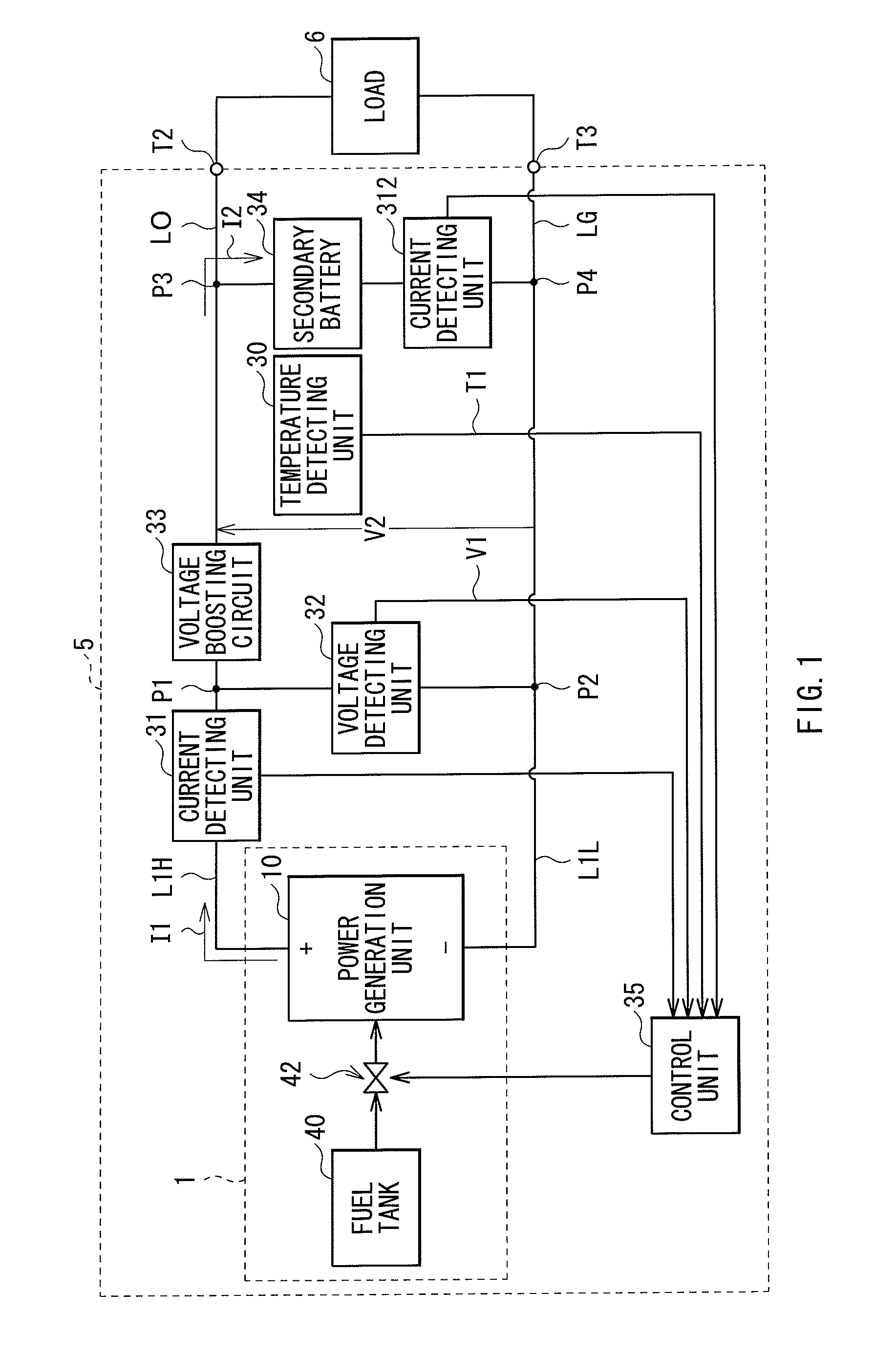
[0025]FIG. 1 illustrates a general configuration of a fuel cell system (fuel cell system 5) according to an embodiment of the present invention. The fuel cell system 5 supplies power for driving a load 6 via output terminals T2 and T3. The fuel supply system 5 includes a fuel cell 1, two current detecting units 311 and 312, a voltage detecting unit 32, a voltage boosting circuit 33, a temperature detecting unit 30, a secondary battery 34, and a control unit 35.

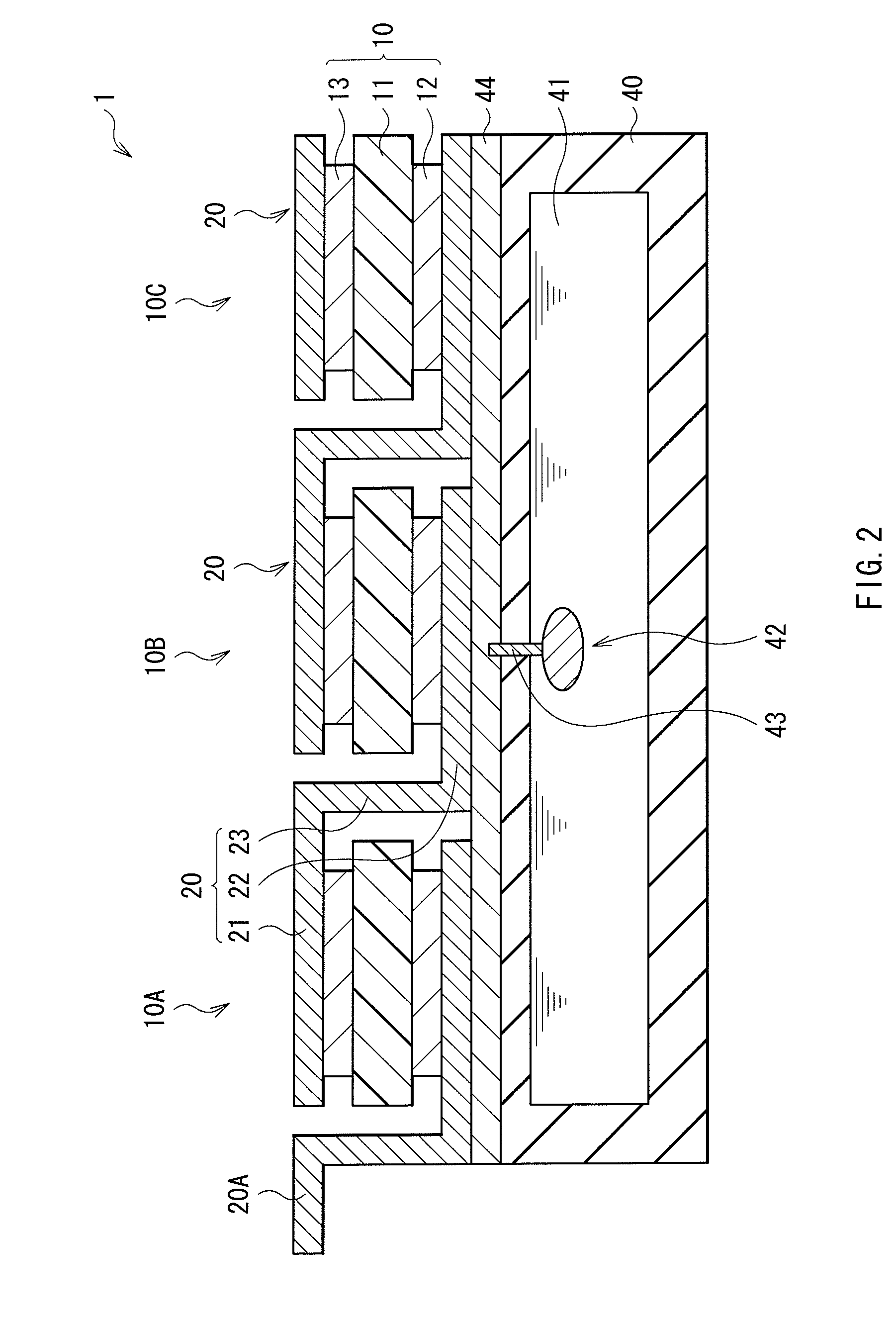
[0026]The fuel cell 1 includes a power generation unit 10, a fuel tank 40, and a fuel pump 42. Note that the detailed configuration of the fuel cell 1 will be described later.

[0027]The power generation unit 10 is a direct methanol power generation unit which generates power by reaction between methanol and oxidant gas (for example, oxygen) and is constructed by including a plurality of unit cells each having a cathode (oxygen electrode) and an anode (fuel electrode). Note tha...

example

[0063]Here, FIG. 8 illustrates an example of the relations among the number of cycles (times), discharged capacity (mAh), and a thickness change amount ΔT (mm) in a lithium ion battery in the case of using a lithium ion battery as the secondary battery 34. In this case, two kinds of cycle tests are conducted: a cycle test of repeating 1C charge and 1C discharge (corresponding to “1C1C” in the diagram); and a cycle test of repeating 2C charge and 1C discharge (corresponding to “2C1C” in the diagram). The “1C charge (1C discharge)” denotes, for example, in the case where current capacity of a lithium ion battery is 1,000 mAh, charging operation (discharging operation) using charging current (discharging current) (that is, 1,000 mA) with which charging (discharging) is completed in one hour. Similarly, for example, in the case where the current capacity of a lithium ion battery is 1,000 mAh, “2C charge” denotes charging operation with charging current (that is, 2,000 mA) with which cha...

application example

2. Modification and Application Example

[0065]Although the present invention has been described above by the embodiment, the invention is not limited to the embodiment but may be variously modified.

[0066]For example, although the case of adjusting the supply amount of the liquid fuel by the fuel pump 42 on the basis of the generated current I1, the charging current I2, the generated voltage V1, and the temperature T1 of the secondary battery 34 which are detected in the control unit 35 has been described in the foregoing embodiment, the invention is not limited to the case. Concretely, for example, in the control unit 35, the supply amount of the liquid fuel by the fuel pump 42 may be adjusted on the basis of only the charging current I2 and the temperature T1 of the secondary battery as the minimum configuration.

[0067]Further, although the case where the control unit 35 controls so that the maximum charging current value Imax decreases exponentially as the detected temperature T1 of...


PUM


Abstract

The present invention provides a small fuel cell system including a secondary battery, in which deterioration in the secondary battery is suppressed regardless of a temperature condition. A control unit adjusts the supply amount of a liquid fluid of a fuel pump so that charging current I2 to a secondary battery becomes smaller than a predetermined maximum charging current value Imax. Consequently, for example, even in the case of using a small secondary battery, the charging current I2 is limited to be smaller than a predetermined upper limit value (maximum charging current value Imax). In addition, a temperature detecting unit detects temperature T1 of the secondary battery and the control unit controls the maximum charging current value Imax in accordance with the detected temperature T1 of the secondary battery. In such a manner, the operation of limiting the charging current I2 in accordance with the temperature T1 of the secondary battery at that time is performed.

Description

TECHNICAL FIELD[0001]The present invention relates to a fuel cell system including a fuel cell and a secondary battery and an electronic device having such a fuel cell system.BACKGROUND ART[0002]Traditionally, since a fuel cell has high power generation efficiency and does not exhaust harmful substances, it is practically used as an industrial or household power generating device or a power source of a satellite, a space ship, or the like. Further, in recent years, development of a fuel cell as a power source for a vehicle such as a car, a bus, or a truck is expanding. Such a fuel cell is classified into an alkaline aqueous solution type, a phosphoric acid type, a molten carbonate type, a solid oxide type, a direct methanol type, and the like. In particular, a direct methanol fuel cell (DMFC) realizes high energy density by using methanol as a fuel hydrogen source and also realizes miniaturization because a reformer is unnecessary. Therefore, such a DMFC is being studied so as to be...

Claims


Application Information

Patent Timeline
IPC IPC(8): H01M10/46
CPCH01M8/04186Y02B90/18H01M8/04738H01M8/04753H01M8/0491H01M8/04917H01M8/1011H01M10/486H01M16/006H01M2250/30Y02E60/523B60L11/1892B60L11/1888Y02E60/50H01M8/04373B60L58/32B60L58/33Y02B90/10Y02T90/40Y02E60/10
Inventor SHIMURA, JUSUKEUCHIDA, YUJI
Owner MURATA MFG CO LTD
Learn More