Multi-antenna wireless communication method and multi-antenna wireless communication device

a wireless communication and multi-antenna technology, applied in wireless commuication services, digital transmission, electrical equipment, etc., can solve the problems of large enhancement of the area where high-throughput transmission can be performed, the number of hand-held antennas cannot be achieved, and the inability to achieve high-speed transmission by multi-stream transfer, etc., to achieve high throughput transmission, easy calculation, and large mimo gain

Inactive Publication Date: 2011-11-03
IWATSU ELECTRIC CO LTD
View PDF4 Cites 110 Cited by
  • Summary
  • Abstract
  • Description
  • Claims
  • Application Information

AI Technical Summary

Benefits of technology

[0065]In the present invention, along with the spatial multiplexing, diversity or beam forming of conventional MIMO technology, further beam forming technique using multi-antenna group is put together with these independently, and therefore a spot area where high throughput transmission of 100 Mbps or more using spatial multiplexing can be enlarged to a plane area. The communications area of VoIP system with conventional MIMO technology like diversity is much smaller than that of narrow-band wireless system such as conventional PHS system. On the other hand, the communication area equivalent to narrow-band wireless system such as conventional PHS system can be realized by the use of combination of conventional diversity and the beam forming according to the present invention.
[0066]In the present invention, the value optimum of diversity combining information in each wireless communication device is determined through two-way training signal transfer between wireless communication devices that perform transmission and reception, and therefore the value optimum of diversity combining information can be easily calculated, and a large MIMO gain can be obtained by performing data transfer by use of this value optimum of diversity combining information even when the number of antennas of the wireless communication device is large. The performance that is equivalent to that of present invention can be realized by conventional MIMO which uses channel matrix of large order, but from the point of cost, power consumption and the amount of arithmetic processing, the implementation of larger scale MIMO is not practical because enormous circuits including radios and baseband circuit is needed.
[0067]Further, the communications area in the conventional MIMO technique can be improved drastically without increasing transmit and receive circuit number if diversity combining in each antenna group is performed in a radio frequency band or without increasing cost and power consumption too much because c

Problems solved by technology

In most of the wireless system which MIMO technology has been introduced, the number of antennas of hand-held terminal is one in general because of power consumption and battery life.
In the case of this, high-speed transmission by use of multi-stream transfer cannot be achieved.
In the diversity gain of this extent, the great enhancement of the area where high-throughput transfer can be performed cannot be expected.
However, the amount of this improvement is small and the area in which throughput takes the value of almost 100 Mbps is limited to the surrounding area near AP and the range of the high-throughput transmission is around 10 m or less in this case after all.
However, the amount of this improvement is still small and the area in which throughput takes the value of almost 100 Mbps is limited to the surrounding area near AP and the range of the high-throughput transmission is around 10 m or less in this case after all.
The radius of service area of the wireless LAN system of IEEE802.11n is said to be around 100 m, however, the area where high-throughput transmission around 100 Mb

Method used


Image

  • Multi-antenna wireless communication method and multi-antenna wireless communication device
  • Multi-antenna wireless communication method and multi-antenna wireless communication device
  • Multi-antenna wireless communication method and multi-antenna wireless communication device

Examples


example 1

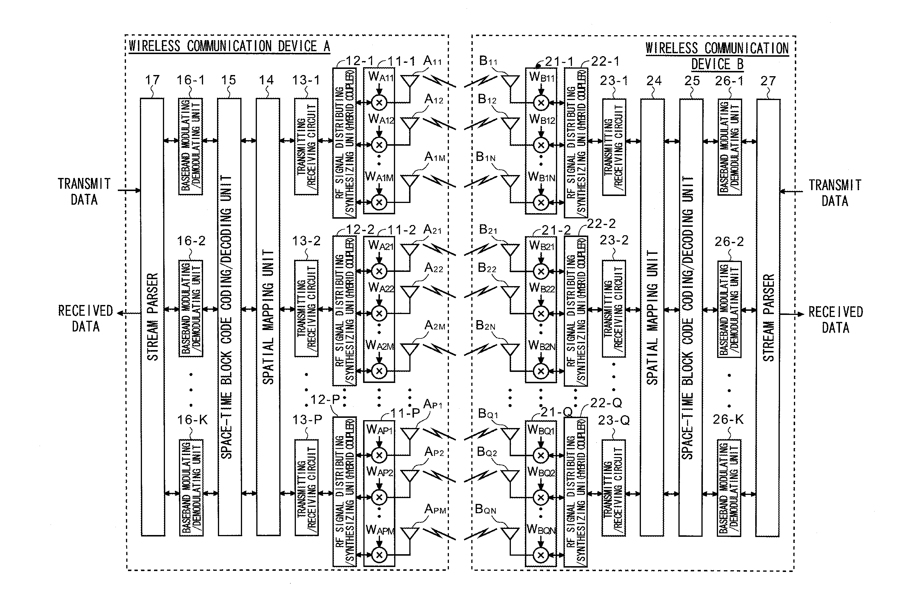
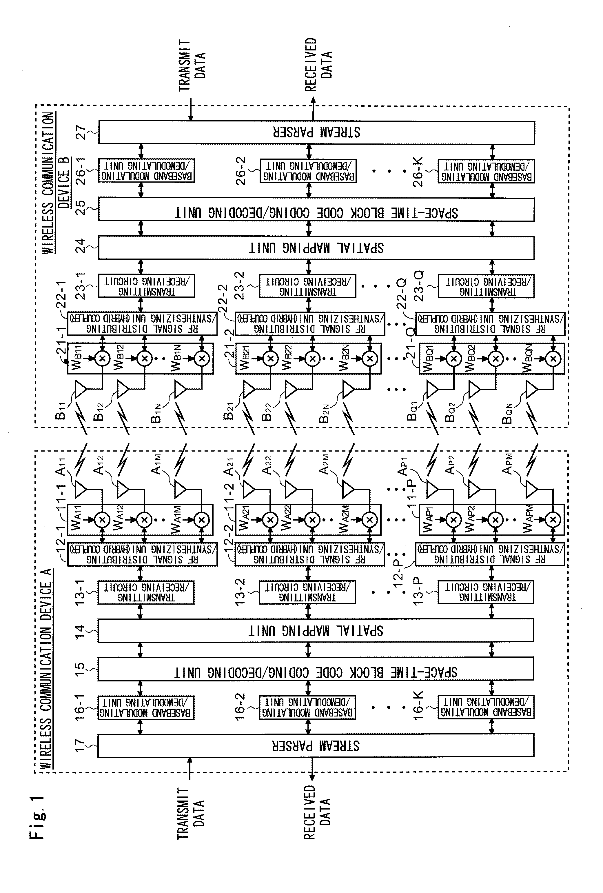
Multi-Stream Transmission without Channel Matrix Information in the Transmitting Side (Direct Mapping)

[0546]In this case, a baseband modulating signal which correspond to different data series with each other is input into each transmitter, respectively, and converted into RF signal, and transmitted from each antenna group. In other word, assuming the pieces of diversity combining weight information VA is expressed by numerical expression (54).

[EQUATION 54]

VA={1 . . . 1 . . . 1}T  (54)

[0547]On the receiving side, channel matrix Hn,m is estimated through training procedure, and the pieces of diversity combining weight information VBp (p is a natural number less than or equal to P) for each data series is calculated by numerical expression (55) using the result of the estimation.

[EQUATION 55]

VBp={vBp1 vBp2 . . . vBpn}T  (55)

example 2

The Multi-Stream Transmission Using Eigenbeam Transmission with Channel Matrix Information in a Transmitting Side

[0548]In the transmitting side, P-th order eigenvectors (P is the number of spatial streams) calculated using channel matrix are set as the pieces of diversity combining weight information Vap (p is a natural number less than or equal to P) of each baseband modulation signal corresponding to each data series. In other word, the pieces of diversity combining weight information VAp are determined using numerical expression (56).

[EQUATION 56]

VAp={vAp1 vAp2 . . . VApm}T  (56)

[0549]Likewise, in the receiving side, P-th order eigenvectors calculated using channel matrix are set as the pieces of diversity combining weight information VBp of each baseband received signal. In other word, the pieces of diversity combining weight information VBp can be obtained using numerical expression (57).

[EQUATION 57]

VBp={vBp1 vBp2 . . . vBpn}T  (57)

example 3

Transmission Diversity Using Space-Time Code with Channel Matrix in a Transmitting Side

[0550]In the transmitting side, distinct a plurality of baseband modulating signals made block code using a code between the space-time are input into a just corresponding transmitter, and it is converted into RF signal, and it is transmitted (direct mapping). In other word, the pieces of diversity combining weight information VA are expressed by numerical expression (58).


PUM


Abstract

The wireless communication devices A and B determine the optimal diversity combining weight information that optimizes a diversity reception state at each antenna group A1, A2, . . . , AP through two-way training signal transfer between the wireless communication devices A and B. This optimal diversity combining weight information is set to each antenna of each antenna group A1, A2, . . . , AP. Wireless communication units A′, B′ perform spacial mapping of signals from antenna group A1, A2, . . . , AP using MIMO technology. Communication area can be enlarged by hierarchization MIMO using the optimal diversity combining weight information.

Description

TECHNICAL FIELD[0001]The present invention relates to a multi-antenna wireless communication method, a multi-antenna wireless communication system, and a multi-antenna wireless communication device, and more particularly, relates to a multi-antenna wireless communication method, a multi-antenna wireless communication system, and a multi-antenna wireless communication device, in which wireless communication is performed with MIMO (Multiple Input Multiple Output) or SIMO (Single Input Multiple Output) technology using a plurality of radios in transmitting side or in receiving side or both and in which an antenna group comprising multiple antennas is used at every transmitting / receiving circuit and each antenna group performs wireless communication with MIMO technology.BACKGROUND ART[0002]The thinness of the semiconductor process rule makes it possible that a plurality of radio circuits are implemented in one semiconductor chip. As a result, the adoption of MIMO technology has become m...

Claims


Application Information

Patent Timeline
IPC IPC(8): H04L27/00H04W4/00
CPCH04B7/043H04B7/0851H04B7/0617
Inventor FUJIMOTO, ATSUSHI
Owner IWATSU ELECTRIC CO LTD
Why Eureka
Try Eureka