Vapor chamber manufacturing method

a manufacturing method and vapor chamber technology, applied in manufacturing tools, semiconductor/solid-state device details, lighting and heating apparatus, etc., can solve the problems of high heat generation, difficult technique, and easily over-exceeding the design standard of the vapor chamber produced, so as to achieve reasonable structure, reduce manufacturing costs, and increase heat dissipation efficiency

Active Publication Date: 2011-11-17
ZHONGSHAN WEIQIANG TECH
View PDF18 Cites 7 Cited by
  • Summary
  • Abstract
  • Description
  • Claims
  • Application Information

AI Technical Summary

Benefits of technology

[0010]The object of the present invention is to provide a vapor chamber with more reasonable structure, higher heat-dissipation efficiency, lower manufacturing costs, and minimized sealing defects.

Problems solved by technology

Nowadays the electronic products on the market are becoming more and more powerful, operating at high speeds can produce a great amount of heat, but the conventional heat dissipating devices used for these products are usually aluminum extruding heat dissipating fins or with fans, which are more or less insufficient for these powerful electronic products.
However this technique is rather difficult: if the wall of the covers is too thin, the covers will easily sink along with the supporting element 03; but if the wall of the covers is too thick, the weight of the vapor chamber produced will easily excess the design standard.
Moreover, as usually a vapor chamber is quite large, the sides thereof are correspondingly long, therefor any small defects of pressing and welding in these sides may become the potentially risky spots in which the covers may split off in a high temperature.
Thus, according to the descriptions above, it is obvious that the conventional manufacturing techniques of vapor chambers are complicated and difficult, consequently low in efficiency and high in manufacturing costs.
Firstly, the vapor chambers or semi-finished vapor chambers produced by foregoing steps all have a fine metal pipe welded in the fluid injection port as a reserved fluid injection pipe, which is shown as FIG. 3, in which 1 is a semi-finished vapor chamber, 101 is the sealing structure, 102 is the fluid injection pipe. The semi-finished vapor chamber with such a structure may be easily damaged because of accidental collision or pressure, consequently to cause higher rejection rate.
This procedure is rather complicated, time consuming and has higher manufacturing cost.
In addition to above, because of the high vacuum in the cavity of the vapor chamber, the approach of using a same port for fluid injecting and vacuum pumping may result in a phenomenon of the rapid vaporization of the working fluid injected while the working fluid is being injected, which may lead to insufficient working fluid in the vapor chamber and consequently a so-called “dry out” phenomenon.

Method used


Image

  • Vapor chamber manufacturing method
  • Vapor chamber manufacturing method
  • Vapor chamber manufacturing method

Examples


Embodiment Construction

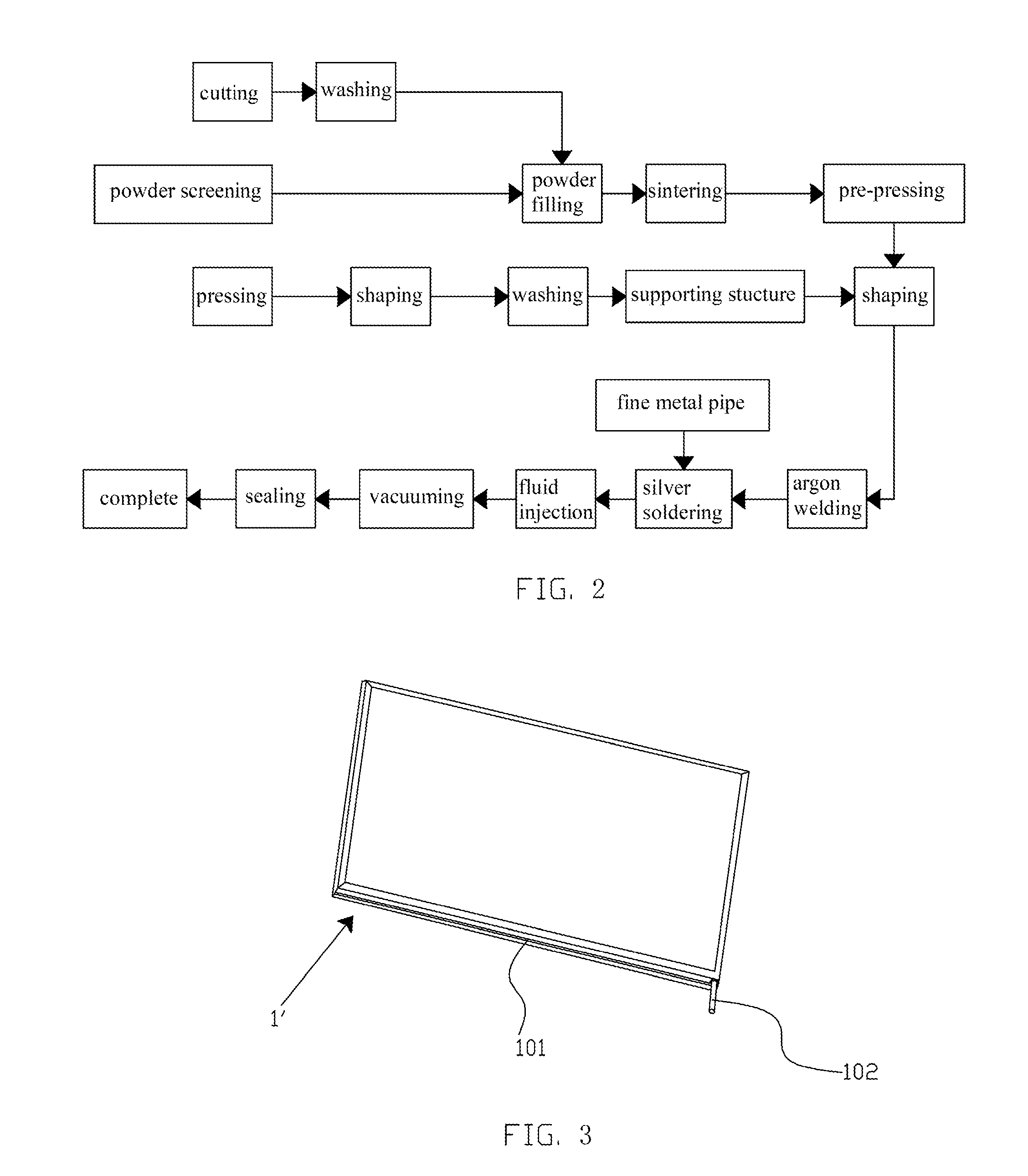
[0043]As shown by the process flow diagram of the first embodiment of the present invention in FIG. 4, wherein the metal material used in this embodiment is a metal tube, the method comprises the following steps:

[0044]Step 1, material preparation: preparing the metal material of the vapor chamber, and cutting the material to predetermined dimensions; as using metal tube, some sub-steps for processing the metal tube are includes:[0045]Cutting: cutting the raw metal tube to predetermined size, straightening the raw metal tube before cutting to ensure the yield of the final product, and washing the metal tube after cutting to ensure the quality of the cavity of the metal tube; and[0046]Rod insertion: inserting a mold rod matching with the internal diameter of the metal tube into the cavity of the metal tube, wherein the mold rod will be sintered with the raw powder in a later step to form the required structure in the cavity of the metal tube.

[0047]Step 2, powder filling and sintering:...


PUM

PropertyMeasurementUnit
thicknessaaaaaaaaaa
thicknessaaaaaaaaaa
thicknessaaaaaaaaaa

Abstract

A vapor chamber manufacturing method, comprises steps of material preparation, powder filling and sintering, pre-punching, supporting structure infilling, the first pressing, the first sealing, fluid injection, and vacuum processing; a sealing structure comprises a semi-finished vapor chamber with a vacuum cavity, a fluid injection port positioned on one side of the vapor chamber, and a supporting structure filled in the vacuum cavity and supporting the shape of the vapor chamber, wherein the fluid injection port is formed of one portion of one side of the vapor chamber by pressing and sealing, no fine metal pipe as fluid injection port is required herein; after the step of fluid injection, an integrated step of vacuum pumping, pressing and sealing is conducted within a vacuum chamber, to provide the product with higher performance and lower rejection rate.

Description

CROSS REFERENCE TO RELATED APPLICATIONS[0001]The present application claims priority under 35 USC 119 to Chinese Patent Application No. 201010180396.4, filed May 15, 2010, the contents of which are incorporated herein by reference.FIELD OF THE INVENTION[0002]The present invention relates to a vapor chamber manufacturing method.BACKGROUND[0003]Nowadays the electronic products on the market are becoming more and more powerful, operating at high speeds can produce a great amount of heat, but the conventional heat dissipating devices used for these products are usually aluminum extruding heat dissipating fins or with fans, which are more or less insufficient for these powerful electronic products. As a result, in the associated industries many manufacturers are continuously to develop new heat dissipating devices using new technologies such as heat pipes and vapor chambers, in which a type of vapor chambers which feature in fluid-vapor two-phase conversion have a widespread use as these...

Claims


Application Information

Patent Timeline
Patent Type & Authority Applications(United States)
IPC IPC(8): B23P25/00
CPCB23P2700/09F28D15/0233F28D15/0283F28D15/046H01L23/427Y10T29/4998F28F2240/00Y10T29/49353H01L2924/0002H01L2924/00
Inventor LEE, KE-CHIN
Owner ZHONGSHAN WEIQIANG TECH
Why Eureka
Try Eureka