[0009]Embodiments of the present invention may, for example, include a device for non-destructively controlling the flow of
polymer flooding EOR fluids at each point of injection at a well-site using a conduit providing a
variable length flow path combined with the centrifugal and other retarding or decelerative forces accessible to a formation engineer by configuring and otherwise arranging the spatial orientation and relative position of each section of such conduit, so as to achieve a never before attained degree of non-damaging flow control density within a compact space.
[0010]Advantageously, such may provide for synchronized multi-point flow control over a
polymer flood so as to coordinate multiple polymer wave fronts from different directions to arrive in a timely manner acting on a common production point, thereby implementing
a site flooding plan in an efficient manner to make the optimal use of polymer possible. Further, such may allow use of a compact apparatus which employs tightly configured seamless conduit and smoothly joined elements that avoid inducing turbulence despite the continuous deceleration caused by passing the polymer fluid through coils of pipework densely assembled in close proximity and using carefully matched internally machined fittings wherever required.
[0011]According to one aspect, an apparatus may enable a formation engineer to relatively finely tune the flow of polymer fluid required to an injection point sweeping oil towards a defined production well, and then permit a relatively less experienced operator to implement a substantially optimal injection plan, based on installing and operating one such apparatus per injection point. Such may advantageously allow the formation engineer and operators of an
injection well-site to refine and / or customize the flow pattern of the site so as to supply a sufficient volume of polymer fluid to each
high resistance injection point while simultaneously limiting the volume of polymer flowing into each
low resistance injection point, without introducing harmful turbulence at any injection point. When the polymer fluid is delivered to all injection points without degradation, the polymer fluid is better able to sweep oil through the reservoir. If appropriate volumes of polymer fluid synchronously travel through their respective flow controllers and then their respective portions of the formation so as to arrive at their designated locations in a timely manner. The combined sweeping effect of the compressive plugs of polymer fluid may move the oil through the reservoir toward a common production point in a more efficient (i.e., no fingering or breakthrough) fashion than otherwise possible. With the many factors that a formation engineer must accommodate and control in order to optimize production at each
injection site, it may be advantageous to install the apparatus at each injection point to provide individually adjustable means for controlling flow without introducing turbulence. The apparatus may permit operators to control the volume of laminar flow of polymer fluid to a particular injection point by varying the
effective length and spatial orientation of the drag inducing conduit through which the polymer fluid is required to pass for delivery to that injection point. Much like the “cars” on a
roller coaster, the
stream of activated polymer fluid moving inside a conduit is subjected not only to the frictional drag between the “wheels and tracks”, corresponding to the tendency for a viscous fluid to adhere to the inner walls of the conduit, but also to the decelerative forces that absorb energy from the
stream of polymer fluid as the
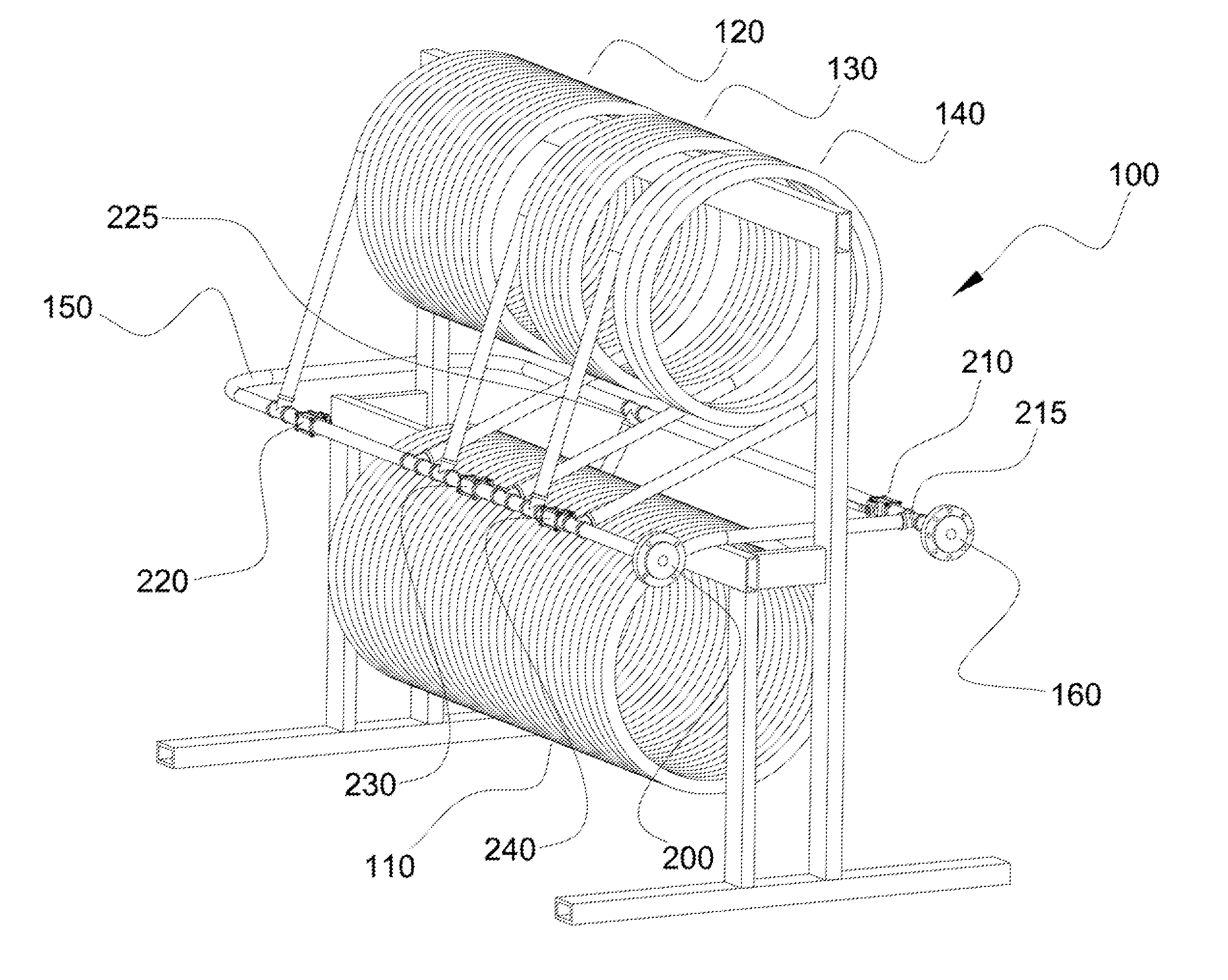
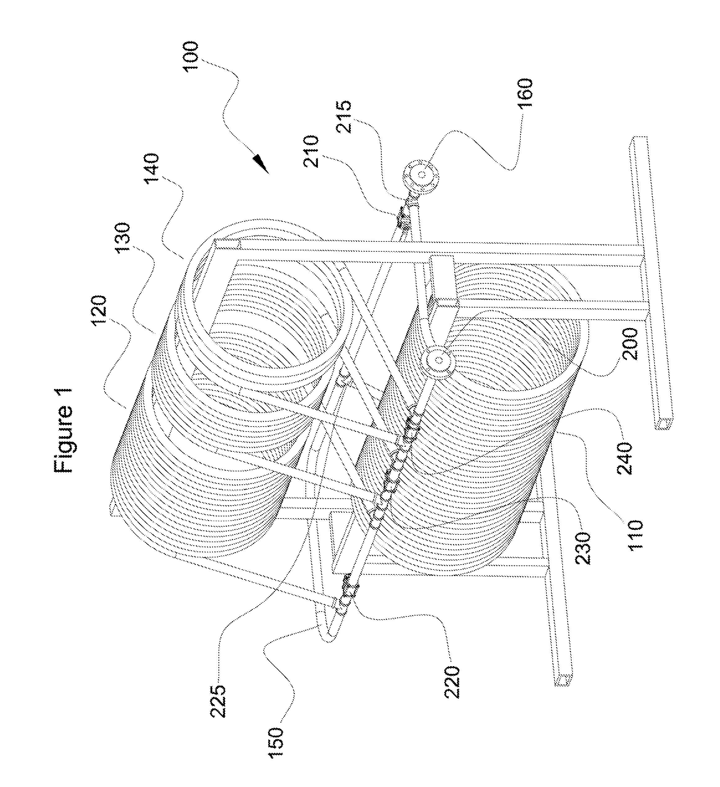
stream changes direction passing around each curve. Such may be particularly enhanced by use of a
helical structure formed by the tubular coils. By this novel means of using the combination of friction and decelerating coils or other loops to
restrict the flow of EOR flooding polymer fluid—
excess energy is gradually dissipated to avoid turbulence such that the attachment points of the polymer molecules are not exposed to sudden change and thereby sheared. Advantageously, the low resistance injection points are supplied by longer and / or more frequent and tightly looped paths of fluid delivery conduit that
delay the arrival of the required volume of polymer fluid into the formation so as to permit an operator to better coordinate delivery with slower moving polymer traveling through
high resistance points.
[0012]Accordingly, there may be provided a compact device for reliably adjusting and controlling flow rate at the point of injection by allowing the operator to introduce or omit different series of coils of differing lengths simply by turning any one or all of the bypass valves in the fluid circuit. Not only does such an apparatus permit operators to accommodate the fluid flow factors of:
viscosity, density, velocity, active conduit length, inner
diameter of available conduit, internal roughness of conduit, transient changes in temperature, and the relative position of supply and
discharge manifolds and lines, but it also takes into account and makes use of the centrifugal forces and other naturally decelerative effects of the combinations of possible spatial orientation that are available to the creative engineer within the efficiently limited volume of space. Thus the apparatus may accordingly be constructed, transported, and housed less expensively than otherwise possible.
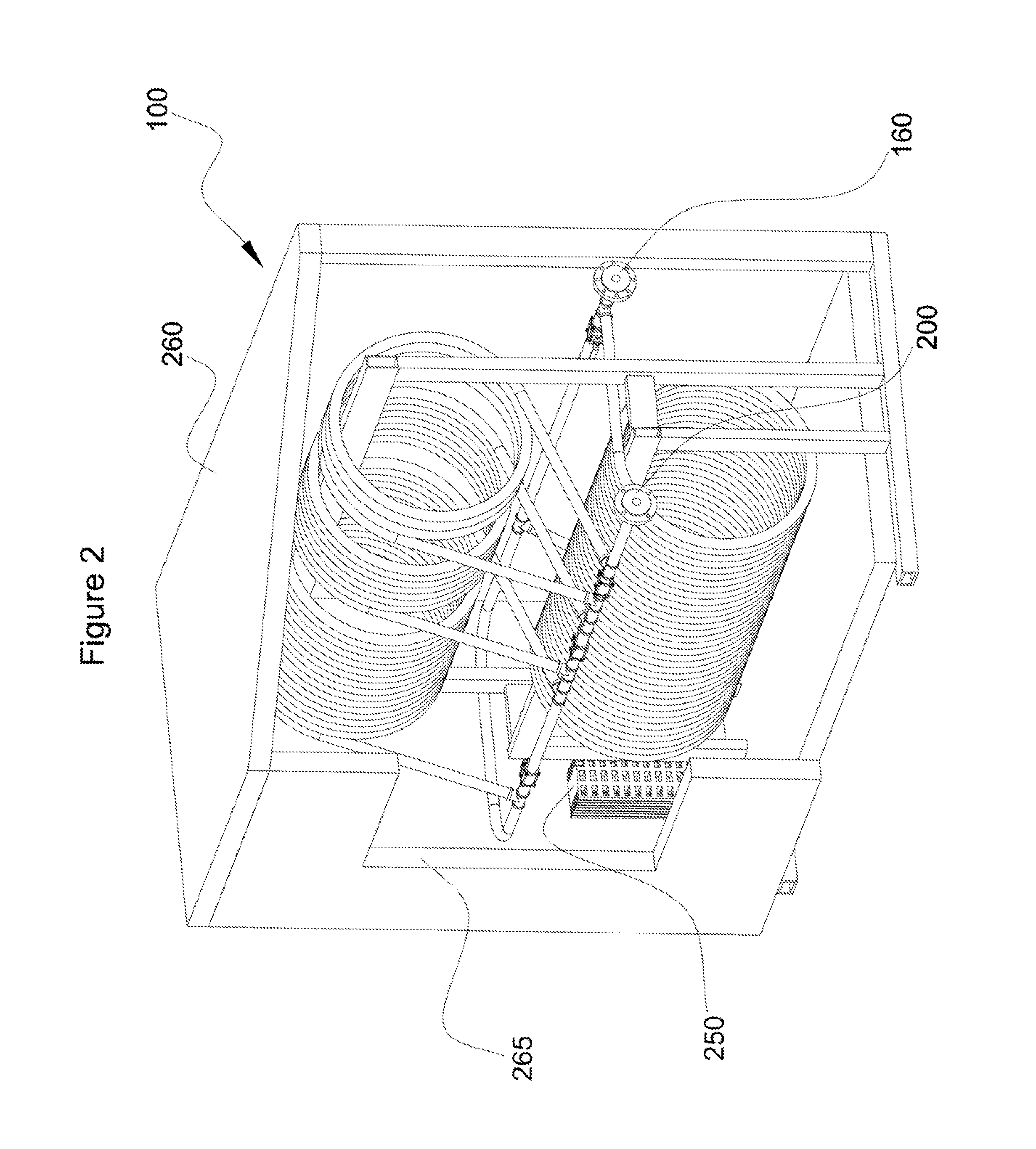
[0014]According to at least one aspect, there is further provided a method of manufacturing such an apparatus incorporating the use of joint-less welded tubes to prevent deadly leaks of sour water. The
present method of manufacturing and the present apparatus may further include a heater that protects aqueous polymer against freezing, and a housing that facilitates
leak detection and protection against mechanical damage during transportation and operation.

