Microfluidic Device

Inactive Publication Date: 2011-12-15
SZITA NICOLAS +1
View PDF3 Cites 26 Cited by
  • Summary
  • Abstract
  • Description
  • Claims
  • Application Information

AI Technical Summary

Benefits of technology

[0009]The present invention provides a microfluidic device which may include a chamber having a fluid inlet, a fluid outlet and a sealable port. In some embodiments, the fluid inlet and the fluid outlet may be positioned to direct fluid flowing from the fluid inlet to the fluid outlet thro

Problems solved by technology

The flushing of cells can also potentially lead to unwanted dissociation of cell colonies.
Although there have been many successes, an important hurdle that still needs to be cleared is the connection between the micro-components of a device and the macro-environment of the world.
The difficulty results from the fact that samples and reagents are typically transferred in quantities of microlitres (μL) to millilitres (or even litres) whereas microfluidic devices consume only nanolitres (nL) or picolitres of samples/reagents due to the size of reaction chambers and channels, which typically have dimensions on the order of microns.
This problem must be overcome for microfluidic devices to be successful, especially for high-throughput applications whe

Method used


Image

  • Microfluidic Device
  • Microfluidic Device
  • Microfluidic Device

Examples


example 1

[0100]Design of a Microfluidic Perfusion Bioreactor

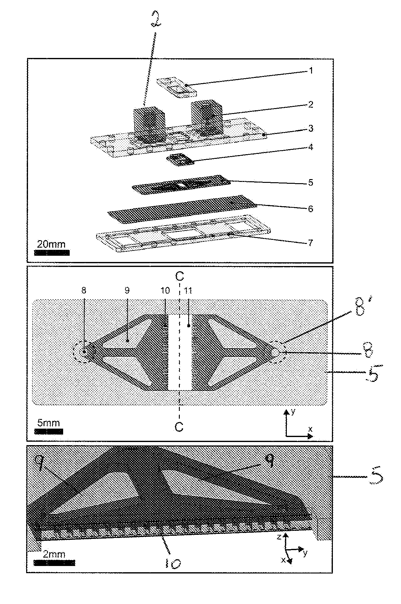
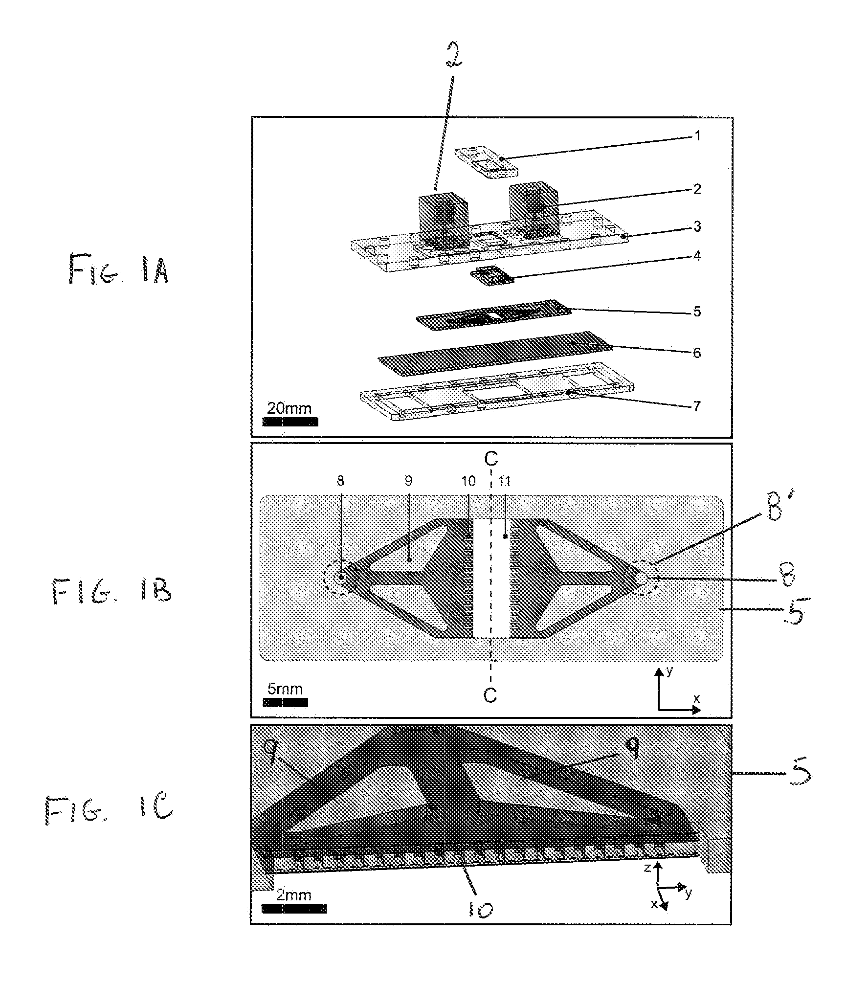
[0101]As shown in FIG. 1A, to integrate a tissue culture polystyrene slide 6, a standard adherent cell culture material, into a microfluidic perfusion bioreactor, a clamp designed with integrated fluidic interconnects 2 was proposed, where a cell culture slide 6 and a microfluidic chip 5 were disposed between a bottom frame 7 and a top plate 3.

[0102]The clamp was held together by screws, where the soft microfluidic chip formed a seal between the culture slide and the interconnects in the top plate. In some embodiments, any fastening mechanism known in the art may be used to hold the MPB together. As shown in FIG. 1A, the top plate 3 included two pockets to hold the gasket 4 and the microfluidic chip 5 and which allowed alignment of the microfluidic chip with the inlet and outlet interconnects 2. Interconnects 2 were mounted on the top plate 3 with screws and a portion of the interconnects extend through a hole in the top plate 3. A ...

example 2

[0115]Fabrication and Assembly of the Microfluidic Bioreactor

[0116]All parts and moulds were designed in a 3D CAD system (SolidWorks 2007, Dassault Systemes SolidWorks, USA). G-code was generated with a CAM program (MasterCam X2, CNC Software, USA) to control the milling process on a micro milling machine (M3400E, Folken Industries, USA).

[0117]To mill the bottom frame 7 and top plate 3 (shown in FIG. 1A), a 3 mm thick poly(carbonate) (PC) sheet (681-637, RS, UK) was machined (8,000 rpm, 104 mm min−1 feedrate) using 2 mm diameter end mills (2 flute standard length, Kyocera Micro Tools, USA).

[0118]The lid 1 as depicted in FIG. 1A was machined from a 5 mm thick PC sheet (681-659, RS, UK) using 2 mm diameter and 1 mm diameter end mills (2 flute standard length, Kyocera Micro Tools, USA).

[0119]Instead of using a SU-8 process, which creates a master for PDMS reproduction, the inventors used a micromilling machine to fabricate moulds for the microfluidic chip (FIG. 5) and the gasket.

[0120]...

example 3

[0154]Imaging

[0155]For the perfusion experiments and the control wells, we used an inverted microscope (Nikon Eclipse TE2000-U, Nikon Corporation, Japan) with a colour microscope camera (Nikon DS-Fil, Nikon Corporation, Japan) for daily inspection and endpoint assays.

[0156]To enhance the immunostaining contrast, the inventors used Photoshop (Photoshop CS3, Adobe Inc., USA).

[0157]Results

[0158]It was found that the hESC in the MPB were healthy and showed no difference compared to the controls demonstrating that the MPB does not have any detrimental effect on the hESC in any way. This was demonstrated by the fact that the pluripotency of the hESC determined by morphology and immunostaining seemed equal or better than in the static control dish, i.e. the hESC had retained their pluripotency.

[0159]Discussion

[0160]The above described chip-to-world device offers a robust method of linking a microfluidic chip with the “macro-world”. The interface includes a loading port, which can easily an...


PUM

PropertyMeasurementUnit
Temperatureaaaaaaaaaa
Fractionaaaaaaaaaa
Timeaaaaaaaaaa

Abstract

The invention relates to a microfluidic device including a chamber having a fluid inlet, a fluid outlet and a sealable port. In some embodiments, the fluid inlet and the fluid outlet may be positioned to direct fluid flowing from the fluid inlet to the fluid outlet through the chamber. Various embodiments may include a sealable port which may be aligned with the chamber to allow material to be placed directly into, or removed from, the chamber from the exterior of the device when the sealable port is open, and to inhibit and/or prevent fluid escaping through the sealable port when the port is sealed.

Description

RELATED APPLICATIONS AND INCORPORATION BY REFERENCE[0001]This application is a continuation-in-part application of international patent application Ser. No. PCT / GB2009 / 002778 filed Nov. 26, 2009, which published as PCT Publication No. WO / 2010 / 061201 on Jun. 3, 2010, which claims benefit of GB patent application Serial No. 0821636.8 filed Nov. 26, 2008.[0002]The foregoing applications, and all documents cited therein or during their prosecution (“appln cited documents”) and all documents cited or referenced in the appin cited documents, and all documents cited or referenced herein (“herein cited documents”), and all documents cited or referenced in herein cited documents, together with any manufacturer's instructions, descriptions, product specifications, and product sheets for any products mentioned herein or in any document incorporated by reference herein, are hereby incorporated herein by reference, and may be employed in the practice of the invention. More specifically, all refe...

Claims


Application Information

Patent Timeline
IPC IPC(8): C12Q1/02B32B37/16C12N5/02F16L13/14C12M1/00B23C3/00
CPCB01L3/502715B01L2200/025B01L2200/027B01L2200/0689B01L2300/0816Y10T409/303752B01L2300/10B01L2400/086C12M23/16C12M23/26C12M29/10B01L2300/0874B01L2300/0627B01L2300/12
Inventor SZITA, NICOLASREICHEN, MARCEL
Owner SZITA NICOLAS
Why Eureka
Try Eureka