Programming method for NAND flash memory device to reduce electrons in channels
a programming method and channel technology, applied in semiconductor devices, digital storage, instruments, etc., can solve problems such as failure in multiple overwrite operations in one page, non-sequential data programming, and physical limitations of nand flash memory, so as to reduce or prevent programming disturbance, and reduce the frequency of page relocation.
- Summary
- Abstract
- Description
- Claims
- Application Information
AI Technical Summary
Benefits of technology
Problems solved by technology
Method used
Image
Examples
first preferred embodiment
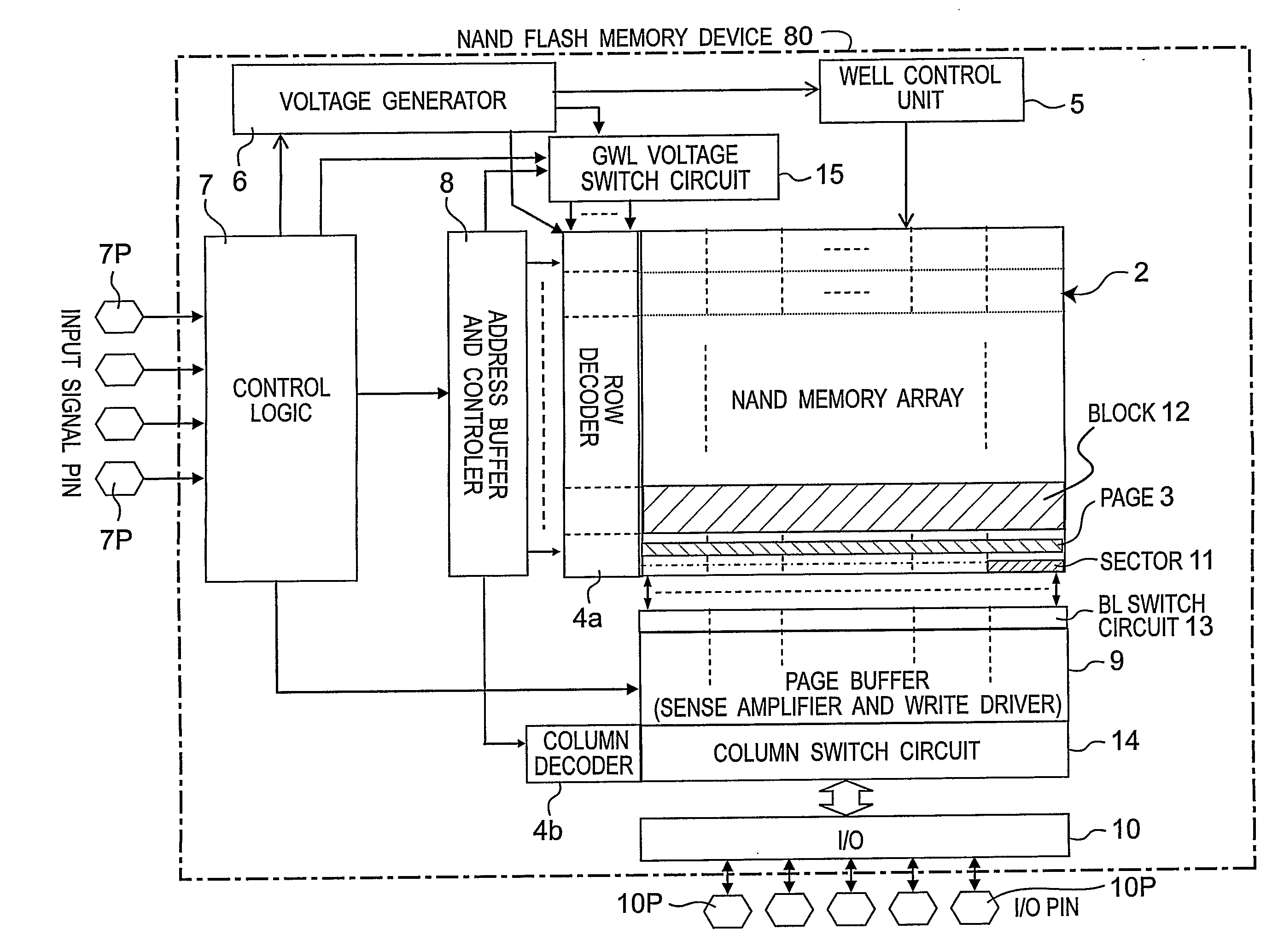
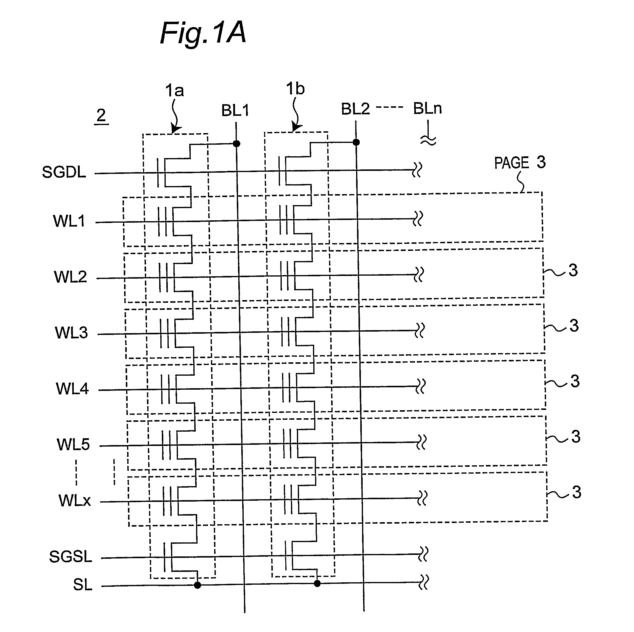
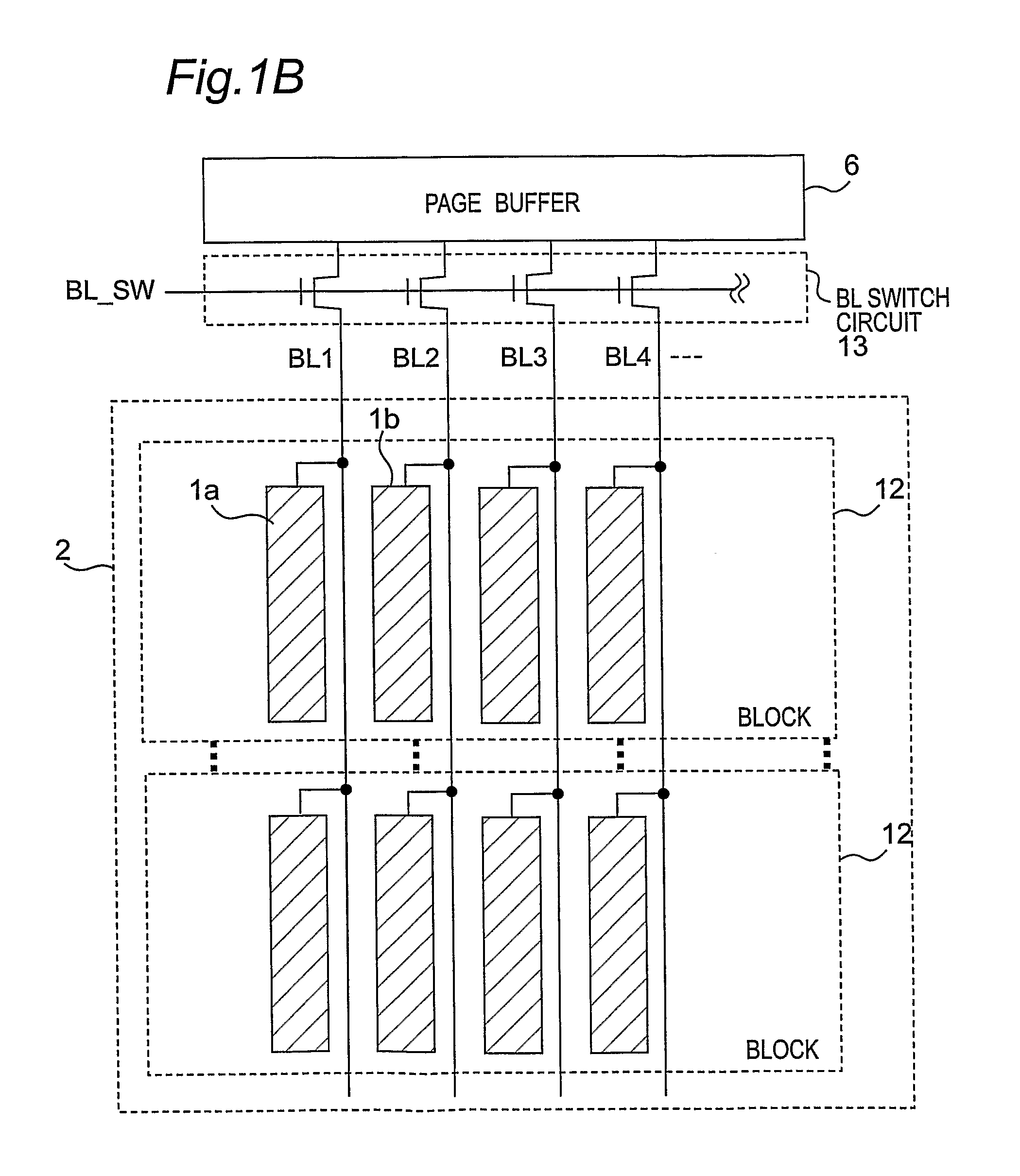
[0168]FIG. 1A is a schematic circuit diagram showing a configuration of a NAND flash memory array 2 of a first preferred embodiment according to the present invention, FIG. 1B is a schematic block diagram of a configuration of the NAND flash memory array 2 of FIG. 1 and peripheral circuits thereof, and FIG. 2 is a longitudinal cross sectional view along a cell string of a configuration of the NAND flash memory array 2 of FIGS. 1A and 1B.
[0169]Referring to FIG. 1, the NAND flash memory array 2 includes a plurality of word lines WL1 to WLx, two selected gate lines SGSL and SGDL, a plurality of bit lines BL1 to BLn, and a source line SL, where x and n are each an integer equal to or larger than two. The parts of the word lines WL1 to WLx spanning over the active area correspond to memory cells. The cell strings composed of the memory cells are disposed below the bit lines BL1 to BLn, where the cell string 1a is connected to the bit line BL1, and the cell string 1b is connected to the b...
second preferred embodiment
[0199]Our proposed programming scheme using the negative gate voltage can be done by the row decoder 4a which will be described below.
[0200]FIG. 20A is a schematic circuit diagram showing a configuration of a high voltage level shifter (referred to as an HVLS hereinafter) 21 and a word line driver (referred to as a WL driver hereinafter) 22 of the row decoder 4a according to a second preferred embodiment of the present invention, FIG. 20B is a schematic circuit diagram showing a configuration of a high voltage level shifter (referred to as an HVMVLS hereinafter) 24 and the WL driver 22 of the row decoder 4a according to the second preferred embodiment of the present invention, and FIG. 21A is a timing chart showing a programming scheme of the second preferred embodiment based on the timing chart of FIG. 12 of the first preferred embodiment. Namely, FIG. 21A shows a programming sequence according to the second preferred embodiment of the present invention, based on the timing chart o...
third preferred embodiment
[0233]The leveraged benefit for file system application brought by this programming method will be described hereinafter.
[0234]FIG. 34A is a graph showing a threshold voltage Vth shift by the program disturb after a partial programming according to a prior art, and FIG. 34B is a graph showing a threshold voltage Vth shift by the program disturb after a partial programming according to the preferred embodiments of the present invention. FIG. 34C is a schematic block diagram showing a unit of partial programming in the page 3 which is used for FIGS. 34A and 34B, and FIG. 34D is a schematic block diagram showing a programming sequence for a storage unit such as a solid-state drive (SSD) which is used for FIG. 34B.
[0235]Although the program disturb occurs seriously in the conventional programming scheme as shown in FIG. 34A, no threshold voltage (Vth) shift is seen after over programming at the same page in our proposed programming method as shown in FIG. 34B, where the program disturb ...
PUM
 Abstract
Description
Claims
Application Information
 - R&D
- Intellectual Property
- Life Sciences
- Materials
- Tech Scout
- Unparalleled Data Quality
- Higher Quality Content
- 60% Fewer Hallucinations
Browse by: Latest US Patents, China's latest patents, Technical Efficacy Thesaurus, Application Domain, Technology Topic, Popular Technical Reports.
© 2025 PatSnap. All rights reserved.Legal|Privacy policy|Modern Slavery Act Transparency Statement|Sitemap|About US| Contact US: help@patsnap.com


