Phosphor wheel configuration for high intensity point source

a high-intensity, point source technology, applied in the field of light sources, can solve the problems of not fully optimizing the operating characteristics of prior art design parameters and/or fabrication methods, and less than desirable in some applications, and achieve the effect of enhancing the stability of light sources from one light pulse to the next, and reducing the size of the phosphor wheel

Active Publication Date: 2011-12-29
MITUTOYO CORP
View PDF0 Cites 4 Cited by
  • Summary
  • Abstract
  • Description
  • Claims
  • Application Information

AI Technical Summary

Benefits of technology

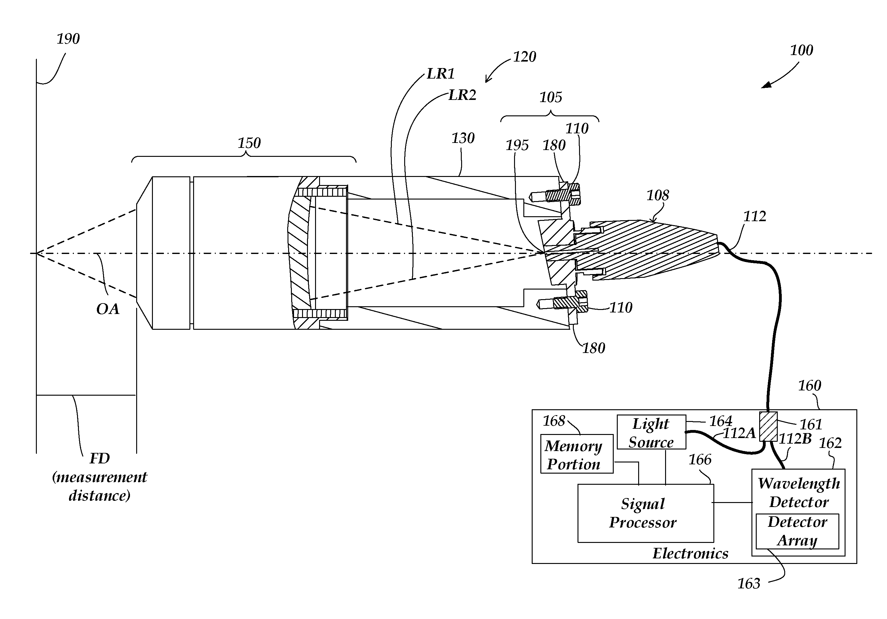
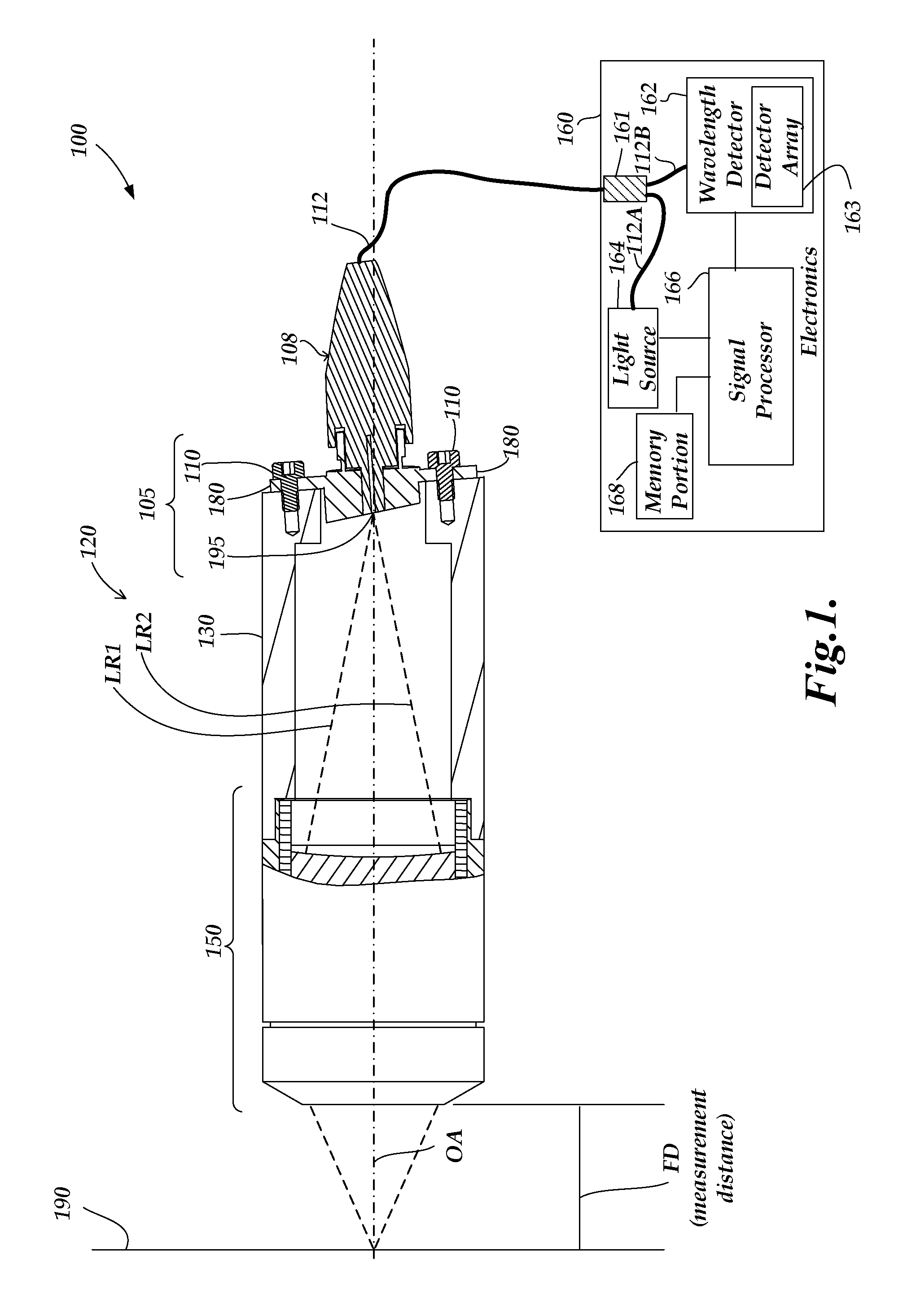
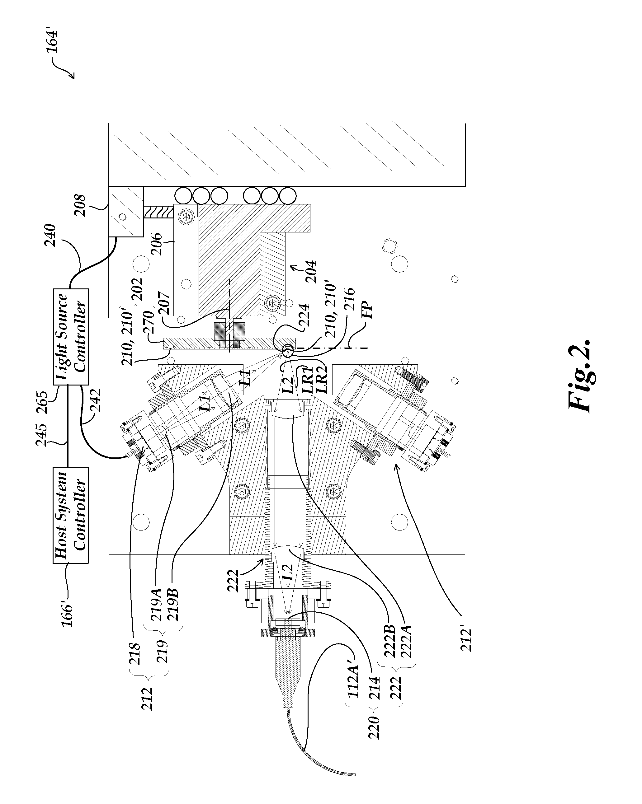
[0011]It will be appreciated that the flatness of the light emitting phosphor at the operational surface is beneficial, particularly in implementations for precision measurement instruments. For example, when the phosphor point source element is utilized as part of a chromatic point sensor system, it is desirable that the operational surface be flat, so that as it is spun, the phosphor particles tightly packed against the operational surface remain at a stable distance within the depth of field (DOF) of the optical system which is used to gather light from the operational track region. In one specific example embodiment, the depth of field of an optical system used to gather light into a 50 um fiber may be approximately 20 um. Thus, in one specific example embodiment, the stability of the light source from one light pulse to the next (e.g., the intensity and/or wavelength stability) may be enhanced when the operational surface flatness is on the order of 20 microns or less, which may be on the order of the particle size of the light emitting phosphor particles in some embodiments.
[0012]In other embodiments, the optical system used to gather light may ha

Problems solved by technology

It has been found that prior art design parameters and/or fabrication methods do not provide fully optimized operating characteristics for the light sources disclosed in the '779 Publicatio

Method used


Image

  • Phosphor wheel configuration for high intensity point source
  • Phosphor wheel configuration for high intensity point source
  • Phosphor wheel configuration for high intensity point source

Examples


first embodiment

[0051]FIG. 3 is an exploded diagram of the rotary actuator 206 and a phosphor point source element 202-1 usable in place of the generic phosphor point source element 202 shown in FIG. 2. As shown in FIG. 3, the phosphor point source element 202-1 comprises a substrate 470, a phosphor region 210′-1 which includes an operational track region 210-1, and a transparent window element 211-1. The window element 211-1 is preferably as light and thin as is practical in some embodiments (e.g., it may have a thickness on the order of 500 um or less, in some embodiments), provided that the overall flatness of the window element 211-1 may be maintained in a manner consistent with the needs of various embodiments outlined below. The window element 211-1 may provide protection and / or support for the phosphor region 210′-1 in some embodiments. However, in other embodiments, it is advantageous to omit the window element 211-1, such that an input and / or output optical fiber end can be positioned prox...

second embodiment

[0064]FIGS. 6A and 6B are cross-section diagrams illustrating how phosphor is arranged in a tightly packed particle arrangement in a phosphor point source element 202-2. The phosphor point source element 202-2 of FIGS. 6A and 6B differs from the previously described phosphor point source element 202-1, in that instead of having an adhesive binding agent reservoir 672 that is separate from the phosphor reservoir 674, a combined reservoir 671 is used for holding both the adhesive binding agent 492 and the phosphor 494. Otherwise, the fabrication and features of the phosphor point source element 202-2 and its derivative alternative embodiments may be understood by analogy with the previous description of the phosphor point source element 202-1.

third embodiment

[0065]FIGS. 7A and 7B are cross-section diagrams illustrating how phosphor is arranged in a tightly packed particle arrangement in a phosphor point source element 202-3. The phosphor point source element 202-3 of FIGS. 7A and 7B differs from the previously described phosphor point source element 202-1, in that the window element 211-3 is not optional, and rather than using reactive centrifugal force to create the tightly packed particle arrangement 496, a mechanical compression configuration is utilized. As illustrated in FIG. 7A, the substrate 770 includes an annular groove 777. An annular compression element 720 (e.g., a metal ring) fits snugly into the annular groove 777. A top surface of the annular compression element 720, along with the sides of the annular groove 777, forms the phosphor reservoir 774. The top surface of the annular compression element 720 also functions as a phosphor track support shoulder 710, as outlined below.

[0066]As one step in fabrication the phosphor 4...


PUM


Abstract

A phosphor point source element comprises a substrate and light emitting phosphor particles arranged on the substrate to provide a circular operational track having a tightly packed particle arrangement adjacent to a flat operational surface of an operational track region. The operational track region is rotated while illuminated at a point to provide a high intensity point source. The tightly packed particle arrangement may be achieved by spinning the phosphor particles in a cavity to compress the phosphor on the substrate at the periphery of the cavity, or by other mechanical compression. The tightly packed phosphor arrangement may either be compressed against a forming element that bounds the cavity, or machined, to provide a flat operational surface. An adhesive binding agent that permeates the phosphor particles may be cured to fix the tightly packed arrangement. A window element may support and/or protect the operational surface, in some embodiments.

Description

[0001]CROSS-REFERENCE(S) TO RELATED APPLICATION(S)[0002]This application is a continuation-in-part of U.S. patent application Ser. No. 12 / 823,050, filed Jun. 24, 2010, priority from the filing date of which is hereby claimed under 35 U.S.C. §120. The key content of U.S. patent application Ser. No. 12 / 823,050 is included herein, and it is otherwise incorporated herein by reference in its entirety.FIELD OF THE INVENTION[0003]The invention relates generally to light sources, and more particularly to high-intensity light sources suitable for use in precision measurement instruments, such as chromatic point sensors.BACKGROUND OF THE INVENTION[0004]Various uses are known for high-intensity broadband light sources. For example, it is known to use such light sources with chromatic confocal techniques in optical height sensors. In such an optical height sensor, as described in U.S. Patent Application Publication No. 2006 / 0109483 A1, which is incorporated herein by reference in its entirety, ...

Claims


Application Information

Patent Timeline
IPC IPC(8): F21V9/16C09K11/00
CPCG01J3/10F21V9/20G01B11/0608G01B2210/50
Inventor EMTMAN, CASEY EDWARDGLADNICK, PAUL GERARDHARSILA, SCOTT ALLEN
Owner MITUTOYO CORP
Why Eureka
Try Eureka