Porous carbon and method of manufacturing same

a technology of porous carbon and manufacturing method, which is applied in the field of porous carbon, can solve the problems of low recovery rate, metal evaporated, and increased cost, and achieve the effect of easy control of the pore diameter

Inactive Publication Date: 2011-12-29
TOYO TANSO KK
View PDF3 Cites 56 Cited by
  • Summary
  • Abstract
  • Description
  • Claims
  • Application Information

AI Technical Summary

Benefits of technology

[0035]The porous carbon of the present invention exhibits significant advantageous effects of reta

Problems solved by technology

However, for commercial use on an industrial scale, this method still has many problems as follows.
For that reason, the recovery and recycling of potassium is attempted, but the recovery rate is low, increasing the cost.
Moreover, alkali metal evaporates during the heating pr

Method used


Image

  • Porous carbon and method of manufacturing same
  • Porous carbon and method of manufacturing same
  • Porous carbon and method of manufacturing same

Examples


example 1

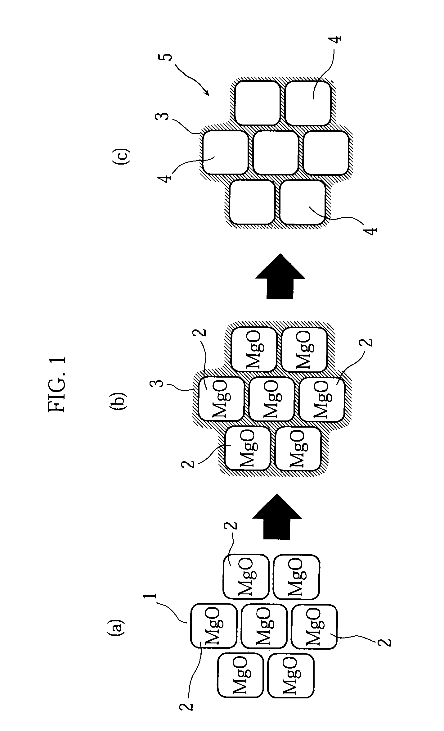
[0056]First, as illustrated in FIG. 1(a), a polyamic acid resin 1 (imide-based resin) as a carbon precursor and magnesium oxide 2 (MgO, average crystallite size 100 nm) as template particles were mixed at a weight ratio of 90:10. Next, as illustrated in FIG. 1(b), the mixture was heat-treated in a nitrogen atmosphere at 1000° C. for 1 hour, to allow the polyamic acid resin to undergo heat decomposition, so that carbon 3 was prepared. Lastly, as illustrated in FIG. 1(c), the resultant carbon 3 was washed with a sulfuric acid solution added at a concentration of 1 mol / L, to dissolve the MgO away completely, whereby porous carbon 5 having a multiplicity of pores 4 was obtained.

[0057]The porous carbon fabricated in this manner is hereinafter referred to as a present invention carbon A1.

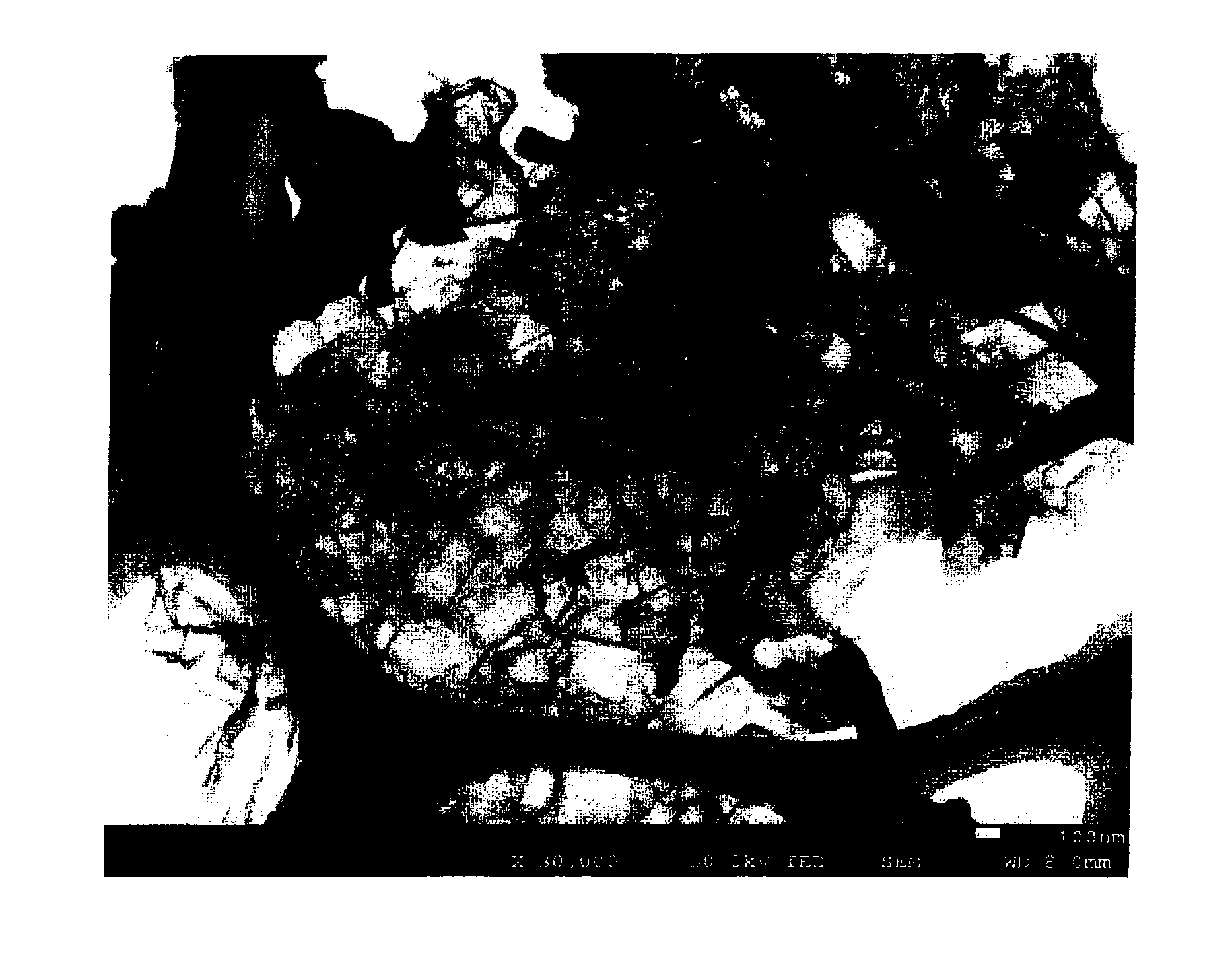
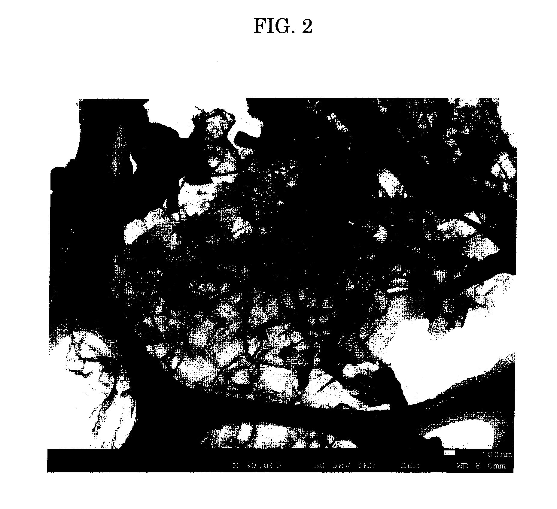
[0058]FIGS. 2 and 3 respectively show a STEM (scanning transmission electron microscope) photograph and a SEM (scanning electron microscope) photograph of the present invention carbon A1. As clearly seen ...

example 2

[0060]Porous carbon was fabricated in the same manner as described in Example 1 above, except that the average crystallite size of the magnesium oxide was 5 nm.

[0061]The porous carbon fabricated in this manner is hereinafter referred to as a present invention carbon A2.

[0062]FIGS. 5 and 6 respectively show a STEM (scanning transmission electron microscope) photograph and a SEM (scanning electron microscope) photograph of the present invention carbon A2. As clearly seen from the two figures, it is observed that the present invention carbon A2 has a three-dimensional network structure (spongy carbon form).

experiment 1

(Experiment 1)

[0067]The relationship between the pressure and the amount of N2 adsorbed was studied for the present invention carbons A1 and A2 as well as the comparative carbons Z1 and Z2. The results are shown in FIG. 7.

[0068]As clearly seen from FIG. 7, when the relative pressure is 1.0, little difference is observed in the amount of N2 adsorbed between the present invention carbons A1, A2 and the comparative carbon Z2. However, when the relative pressure is in the range of 0 to to 0.1, it is observed that the present invention carbons A1 and A2 adsorb large amounts of N2, while the comparative carbon Z2 adsorbs little N2. It is also observed that the amount of N2 adsorbed is very small for the comparative carbon Z1 over the entire range.

[0069]The reason is believed to be as follows. In the present invention carbons A1 and A2, mesopores and micropores disposed at the positions facing the mesopores are formed. As a result, the micropores adsorb N2 when the relative pressure is low...


PUM

PropertyMeasurementUnit
Temperatureaaaaaaaaaa
Fractionaaaaaaaaaa

Abstract

A porous carbon that retains a three-dimensional network structure and enables the pore diameters of mesopores and micropores to be controlled easily is provided. A method of manufacturing the porous carbon is also provided. The porous carbon is fabricated by mixing a polyamic acid resin 1 as a carbon precursor with magnesium oxide 2 as template particles, heat-treating the mixture in a nitrogen atmosphere at 1000° C. for 1 hour to cause the polyamic acid resin to undergo heat decomposition, and washing the resultant sample with a sulfuric acid solution at a concentration of 1 mol/L to dissolve MgO away.

Description

TECHNICAL FIELD[0001]The present invention relates to a porous carbon and methods of manufacturing the porous carbon. More particularly, the invention relates to a porous carbon fabricated using a source material with a relatively high carbon yield, and a method of manufacturing the same.BACKGROUND ART[0002]It has been known that activated carbon, which is a porous carbon, may be fabricated by a method in which a source material is heated and carbonized under a non-oxidizing atmosphere. Examples of the source material include: plant-originating source materials such as lignin, cellulosic substances including wool pulp, saw dust, coconut husk, cottonseed hull, and chaff, starchy substances including foxtail millet, Japanese barnyard millet, and corn; mineral-originating source materials such as coal, tar, and petroleum pitch; and synthetic resins such as phenolic resin and polyacrylonitrile. The techniques for treating the carbonized substances of these source materials with a chemic...

Claims


Application Information

Patent Timeline
IPC IPC(8): C01B31/00B29C71/02
CPCB82Y30/00C01P2006/16C04B35/524C04B38/0032C04B2235/3206C04B2235/3208C04B2235/5409C04B2235/5454C04B2235/6028C04B2235/72C04B2235/723C04B2235/726C04B2235/727C01B31/00C01P2006/12C04B35/52C04B38/0058C04B38/0064C04B38/04C01B32/00C01B32/30C01B32/318B01J20/28C01P2006/13
Inventor MORISHITA, TAKAHIRO
Owner TOYO TANSO KK
Why Eureka
Try Eureka