Pyrolytic reactor

a pyrolysis reactor and reactor technology, applied in the field of pyrolysis reactors, can solve the problems of destroying the environment, unable to economically viable pyrolysis reactors, and unable to recover discarded tires, so as to prevent environmental pollution

Active Publication Date: 2012-01-12
T D E RECOVERY TECH LT
View PDF10 Cites 15 Cited by
  • Summary
  • Abstract
  • Description
  • Claims
  • Application Information

AI Technical Summary

Benefits of technology

[0034]In one aspect, the reactor further comprises isolating means for isolating the product vapors and gases from the feeding device, thereby preventing environmental pollution upon charging the feeding system.

Problems solved by technology

At present, the recovery of discarded tires remains a serious problem, despite certain achievements in this field.
A large number of tires are located outside of the stockpiles, and pollute the environment.
Many prior art reactors convert the rubber containing materials of tires into the aforementioned products by heat induced decomposition, but are impractical due to the resulting environmental pollution or due to cost ineffectiveness.
This pyrolytic reactor is not economically viable as small scrap tire particles are fed thereto, resulting in high pre-processing costs.
This process is also not cost effective due to the high pre-processing costs involved in shredding the tires to small pieces.
In addition to the relatively high costs involved in comminuting the feedstock pieces, an additional disadvantage of this system is that the combustion products flow across the exterior of the outer drum and indirectly transfer heat to the converter drum only by convection, while the wall of the converter drum transfers heat to the feedstock pieces only by conduction.

Method used


Image

  • Pyrolytic reactor
  • Pyrolytic reactor
  • Pyrolytic reactor

Examples


example

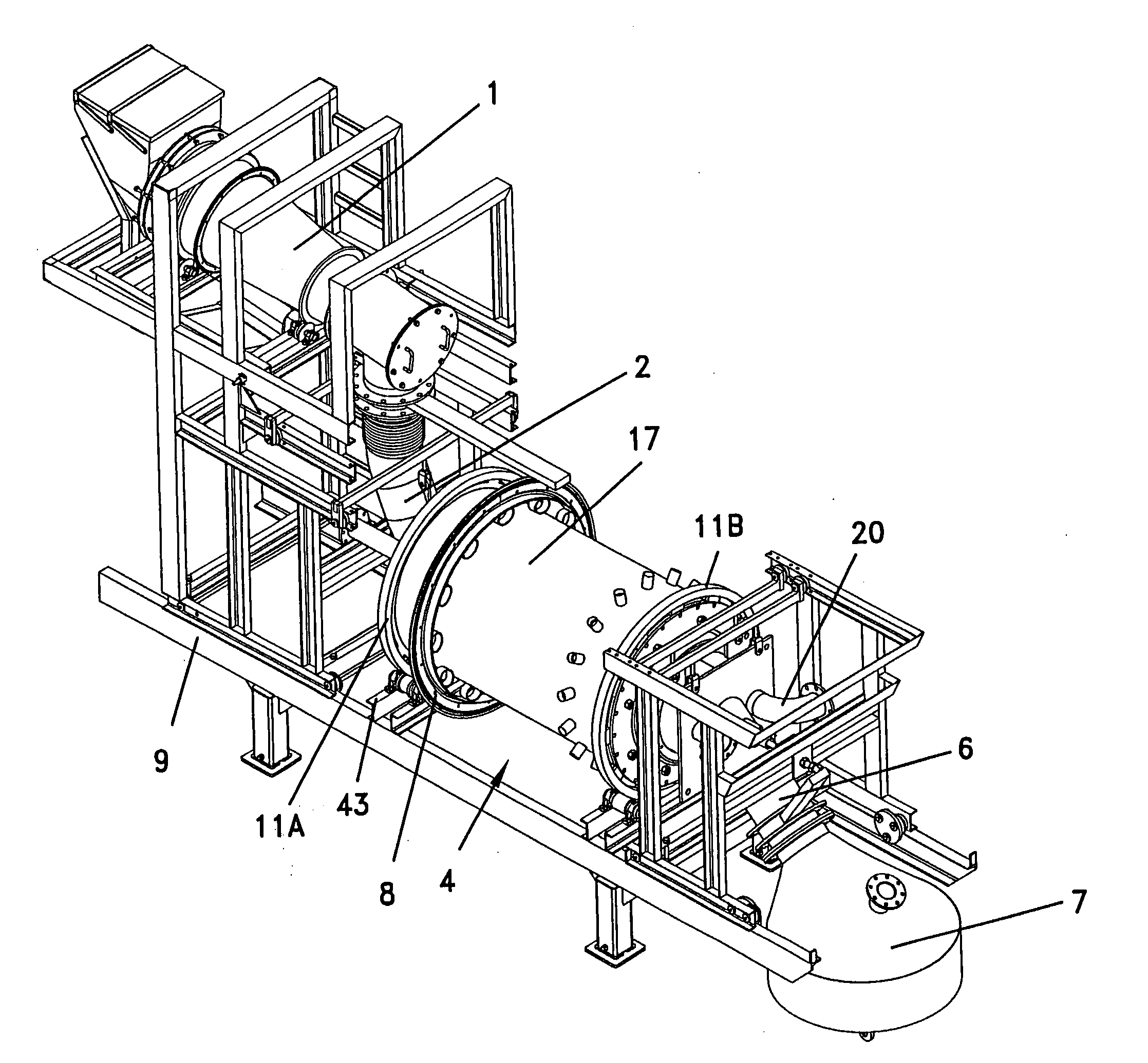
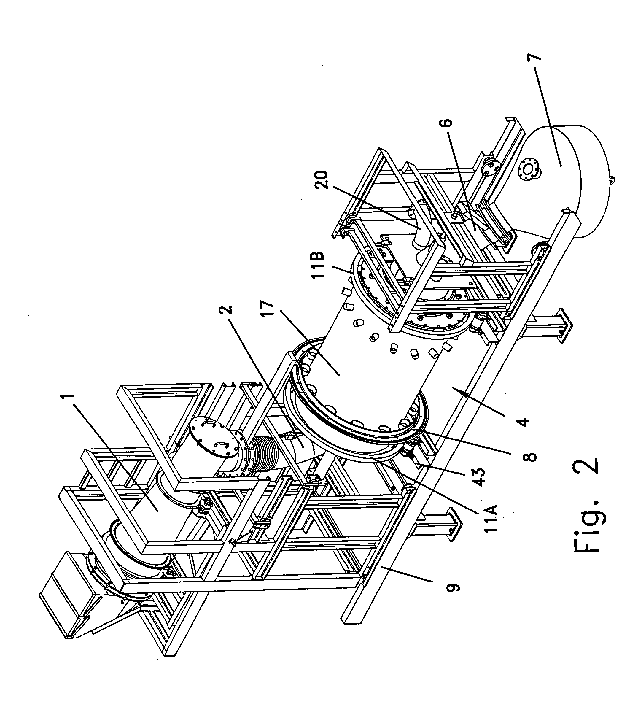
[0096]The pyrolytic reactor comprised an inner drum with a diameter of 1 m, and a coaxial outer drum defining a clearance of 30 mm. The circumferential wall of the inner drum was perforated with 5 mm apertures such that the uniform distance between adjacent apertures was 5 mm. The reactor was inclined at an angle of 1 degree downwards. The reactor was rotated at a constant angular velocity of 0.25 rpm. Tire pieces with a size ranging from 200-300 mm and having metal cords protruding from the rubber base were continuously fed at a rate of 100 kg / hr.

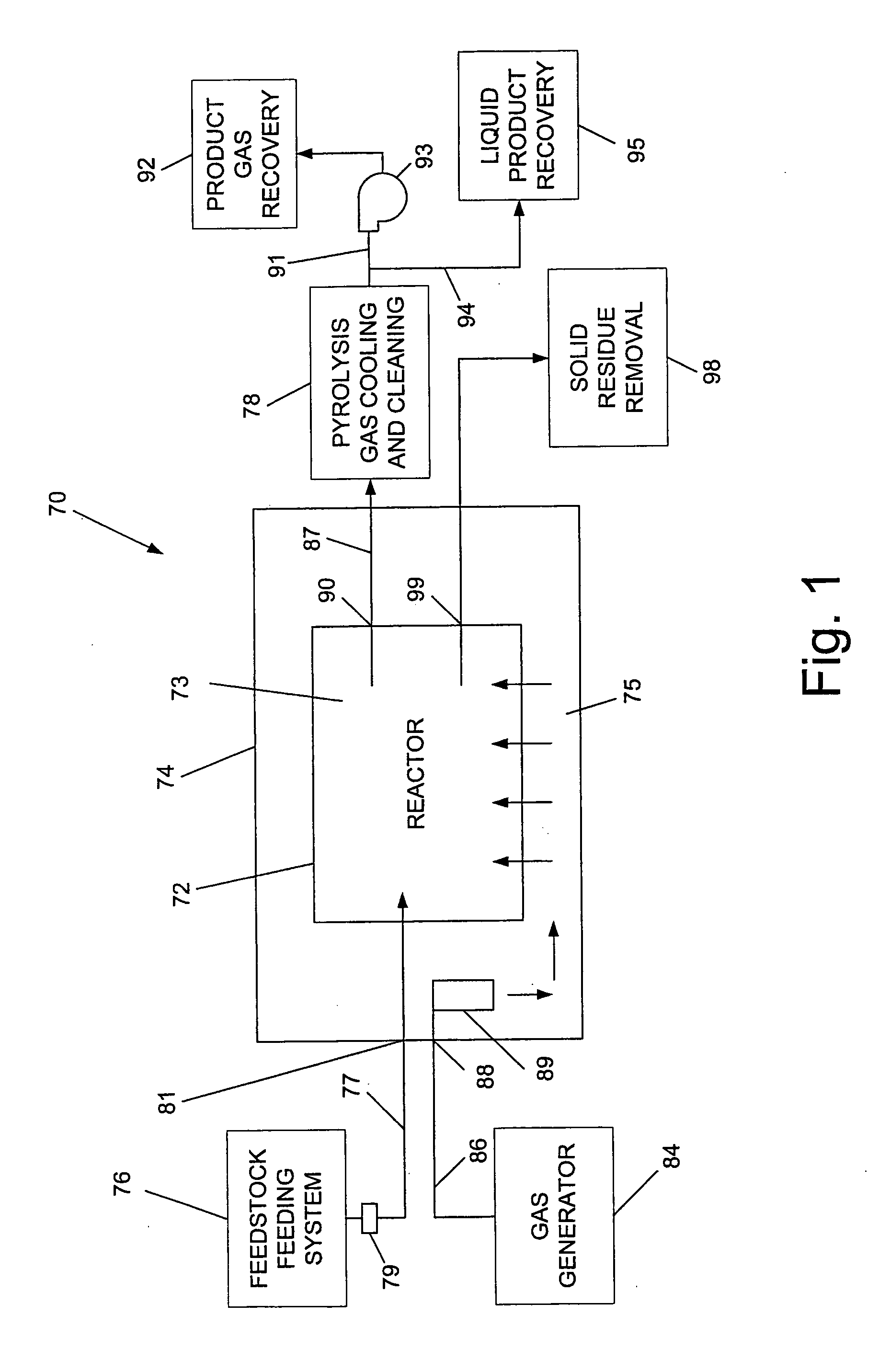
[0097]The heat carrier gases, which were directed to the clearance and then into the inner drum interior via the apertures, were the product of gasification of the solid, pyrolyzed carbonized residue. In addition to the solid residue, steam and air were introduced to a gas generator. The gas generator was initially heated by the combustion of a standard mixture of propane and butane from a cylinder, achieving a temperature within the gas g...


PUM

PropertyMeasurementUnit
sizeaaaaaaaaaa
temperaturesaaaaaaaaaa
size ratioaaaaaaaaaa

Abstract

A pyrolytic reactor, comprising an inner drum having a circumferential wall formed with a plurality of apertures, an outer drum surrounding the inner drum and defining a clearance therebetween, a feeding device for feeding a plurality of feedstock pieces to the interior of the inner drum, an inlet port through which heat carrier gases flow and are directed to said clearance, for introduction of the heat carrier gases via said plurality of apertures to the inner drum interior and causing pyrolysis of the fed feedstock pieces, a conveyor for transporting a plurality of solid residue pieces produced from a pyrolytic process, and an outlet port through which product vapors and gases, heat depleted heat carrier gases, and the plurality of solid residue pieces are discharged.

Description

FIELD OF THE INVENTION[0001]The present invention relates to a pyrolytic reactor for processing organic based raw materials, e.g. discarded tires, resulting in gaseous and liquid products which are usable for example to generate electrical power. More particularly, the reactor is designed such that the heat transfer between heat carrier gases and the raw material is sufficiently intensive so that a good pyrolytic performance can be achieved with respect to relatively large feedstock pieces that are fed to the reactor, to obviate the high preprocessing costs associated with prior art reactors.BACKGROUND OF THE INVENTION[0002]At present, the recovery of discarded tires remains a serious problem, despite certain achievements in this field. Some discarded tires are utilized in civil engineering and in road construction, as well as in the manufacturing of different goods. Nevertheless about 30% of discarded tires, and in some countries, up to 80%, are still disposed in stockpiles. A larg...

Claims


Application Information

Patent Timeline
Patent Type & Authority Applications(United States)
IPC IPC(8): C10B5/00
CPCC10B1/10F27D3/16C10B53/07C10J3/66C10J2300/094C10J2300/0946C10J2300/0956C10J2300/0973F27B7/00F27B7/10F27B7/20Y02E20/12C10B51/00F23G5/0276F23G5/20F27B7/362B65G11/206F27B7/42C10B49/04Y02P20/143
Inventor BRONSHTEIN, ALEXANDER P.SKOP, MENACHEM L.WEISS, MOSHEJAKOBOWITCH, DAVID SHALOM
Owner T D E RECOVERY TECH LT
Why Eureka
Try Eureka