HTS coated conductor with particle inclusions, and method of production of an HTS coated conductor

a technology of hts coating and conductor, which is applied in the direction of superconductor details, superconductor devices, crystal growth process, etc., can solve the problems of reducing the critical current and critical magnetic field, electrical losses, and insufficient current performance of low temperature superconductors (typically used in this area), and achieve good pinning effect, good pinning effect, and not too much distortion of hts layer lattice

Inactive Publication Date: 2012-01-19
BRUKER HTS
View PDF6 Cites 5 Cited by
  • Summary
  • Abstract
  • Description
  • Claims
  • Application Information

AI Technical Summary

Benefits of technology

[0034]The mean radius is the radius of a perfect sphere having a volume corresponding to the average volume of the particle inclusions of said part. In this size regime, good pinning effects are achieved while at the same time not distorting the HTS layer lattice too much. It should be noted that also preferred are sizes (mean radius) of the particle inclusions of said part are between 2 nm and 50 nm, and further between 3 nm and 30 nm.
[0035]A preferred embodime...

Problems solved by technology

This performance is important for high field magnets used in e.g. NMR where fields are so high that the current performance of low temperature superconductors (typically used in this area) becomes insufficient.
This redistrib...

Method used


Image

  • HTS coated conductor with particle inclusions, and method of production of an HTS coated conductor
  • HTS coated conductor with particle inclusions, and method of production of an HTS coated conductor
  • HTS coated conductor with particle inclusions, and method of production of an HTS coated conductor

Examples


first embodiment

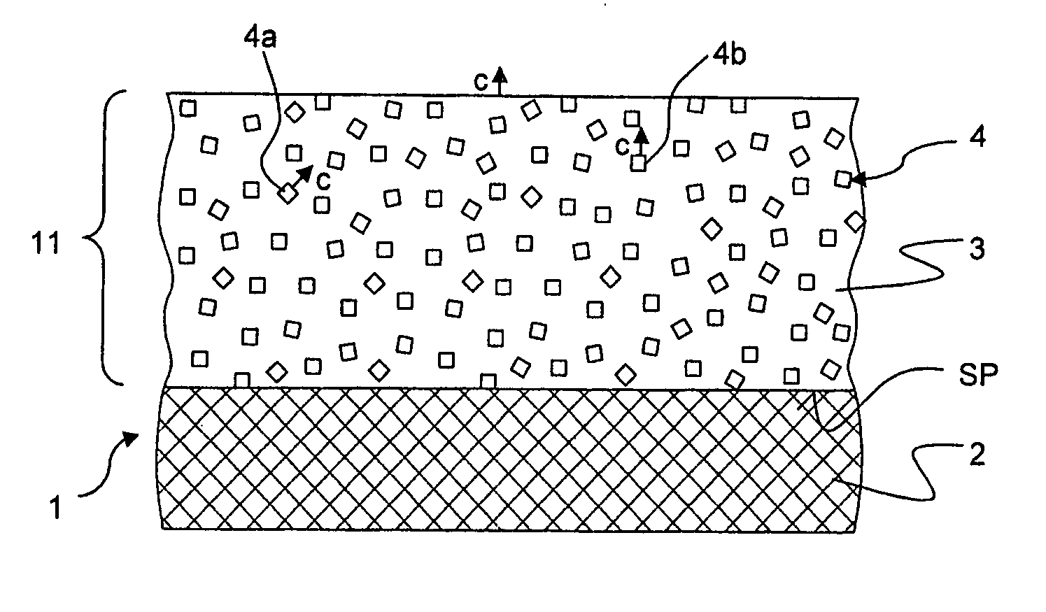
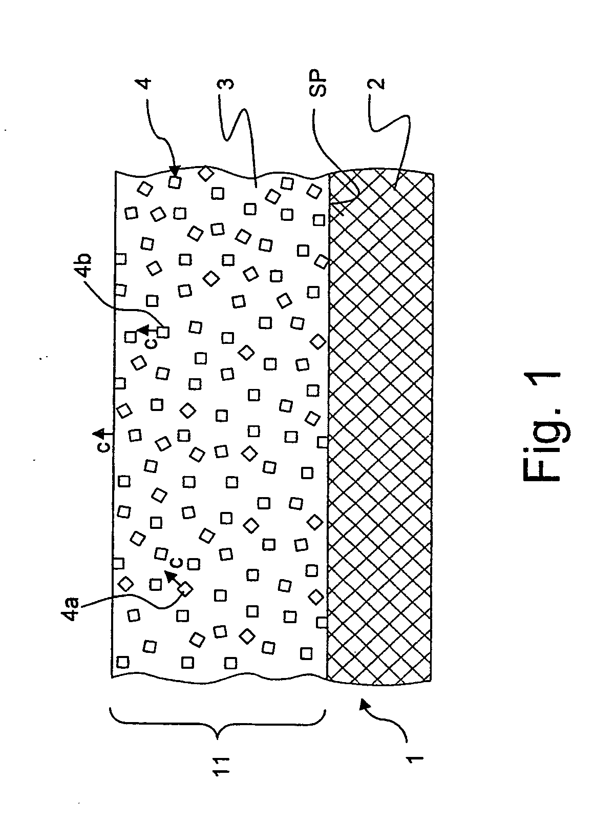
[0056]FIG. 1 shows a schematic, cross-sectional view of an inventive HTS coated conductor 1, comprising a substrate 2, e.g. of SrTiO3 or of steel tape type. The substrate 1 is typically equipped with a buffer layer, e.g. of CeO2 (not shown, for simplification). On top of the substrate 2 (or its buffer layer, if applicable), there is an epitaxial HTS layer 3, here of YBCO material. The HTS material of the HTS layer 3 is oriented such that the c-axis of the YBCO crystal (or its grains, respectively) is perpendicular to the substrate plane SP (compare the arrow c, on top of the HTS layer 3, indicating the c-axis direction).

[0057]Within the HTS layer 3, there are particle inclusions 4, which are here randomly distributed within HIS layer 3. In the example shown, all these particle inclusions 4 are of single crystalline YBCO material, with the same stoichiometry and as the material of the HTS layer 3, and with the same crystal structure. However, the particle inclusions 4 are also random...

second embodiment

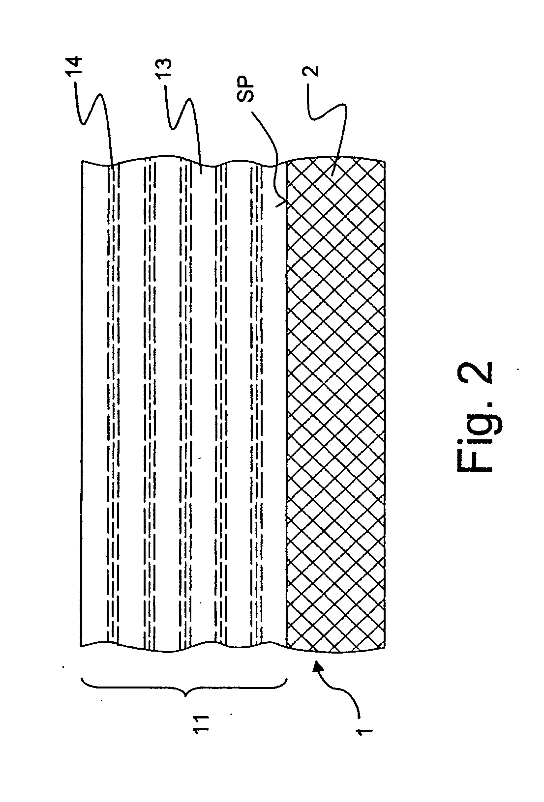
[0063]FIG. 2 shows an inventive HTS coated conductor 1. Here a HIS layer 11 based e.g. on YBCO as HTS material, deposited on a (possibly buffered) substrate 2, comprises a number of first sublayers 14 and second sublayers 13. Particle inclusions (not shown in detail) derived from the HTS material are here confined to the first sublayers 14; these first sublayers 14 typically contain, in addition to the particle inclusions, HTS material and / or buffer material, such as CeO2, which is typically used to grow the used HTS material on top of, and / or an amorphous phase (which is not superconducting) of the stoichiometry of the HTS layer material. The first sublayers 14 are separated by the second sublayers 13, which are made of the HTS material and contain no particle inclusions derived from the HTS material (or at least contain much less particle inclusions derived from the HIS material as compared to the first sublayers 14, such as at least ten times less with respect to the volume fract...


PUM


Abstract

A high temperature superconductor (=HTS) coated conductor (1), comprising an HTS layer (11) deposited epitaxially on a substrate (2), wherein the HTS layer (11) exhibits a lattice with a specific crystal axis being oriented perpendicular to the substrate plane (SP), in particular wherein the HTS layer material is of ReBCO type and the c-axis (c) is oriented perpendicular to the substrate plane (SP), wherein the HIS layer (11) comprises particle inclusions (4),in particular wherein the particle inclusions (4) may be used to introduce pinning of magnetic flux, is characterized in that at least a part (4a) of the particle inclusions (4) are formed of the same material as the HTS layer (11), and/or of chemical fractions of the material of the HTS layer (11), such that the average stoichiometry of said part (4a) of the particle inclusions (4) corresponds to the stoichiometry of the HTS layer (11), and that the particle inclusions of said part (4a) are discontinuities of the lattice of the HTS layer (11). A more simple method for producing a HTS coated conductor with reduced losses, and with improved critical current and critical magnetic field is thereby provided.

Description

[0001]The application claims Paris Convention priority of EP 10 170 033.4 filed Jul. 19, 2010 the complete disclosure of which is hereby incorporated by reference.BACKGROUND OF THE INVENTION[0002]The invention relates to a high temperature superconductor (=HTS) coated conductor,[0003]comprising an HTS layer deposited epitaxially on a substrate,[0004]wherein the HTS layer exhibits a lattice with a specific crystal axis being oriented perpendicular to the substrate plane,[0005]in particular wherein the HTS layer material is of ReBCO type and the c-axis is oriented perpendicular to the substrate plane,[0006]wherein the HTS layer comprises particle inclusions,[0007]in particular wherein the particle inclusions may be used to introduce pinning of magnetic flux.[0008]Such a method is known from US 2006 / 0025310 A1.[0009]Superconductors are used to transport electrical current at low resistance, and thus at low power losses. Superconductors require cryogenic cooling in order to ensure the s...

Claims


Application Information

Patent Timeline
IPC IPC(8): H01L39/12H01L39/24H01L39/02B82Y99/00
CPCH01L39/126H01L39/2483H01L39/2448H01L39/128H10N60/858H10N60/857H10N60/0521H10N60/0828
Inventor USOSKIN, ALEXANDERSCHLENGA, KLAUS
Owner BRUKER HTS
Why Eureka
Try Eureka