MEMS oscillator

a technology of oscillator and oscillator, which is applied in the direction of oscillation generator, influence generator, electrical apparatus, etc., can solve the problems of quartz resonators that cannot be easily integrated on a si chip, the packaging technology used to encapsulate quartz crystals does not lend itself well to miniaturization, and the miniaturization of rtcs and rfos

Active Publication Date: 2012-02-09
NXP BV
View PDF6 Cites 10 Cited by
  • Summary
  • Abstract
  • Description
  • Claims
  • Application Information

AI Technical Summary

Benefits of technology

[0023]The control circuitry can be adapted to apply voltages with opposite polarity to the drive electrodes with respect to a reference voltage, weighted in magnitude with respect to the capacitance between the respective drive electrode and the sense electrode. This provides a way to offset the effect of the parasitic capacitances even if they have different magnitude.

Problems solved by technology

The main reason for this is because the packaging technology being used to encapsulate the quartz crystal does not lend itself well to miniaturization.
Furthermore, quartz resonators cannot be integrated easily on a Si chip.
Therefore, the integration of a complete oscillator consisting of the crystal and amplifier cannot be realized on a single chip and further prohibits the miniaturization of RTCs and RFOs.
The production cost associated with micro-machining decreases when the area occupied by a single device decreases.
For quartz resonators, the production cost increases when the size of the resonator decreases as a result of the assembly-like production process that is being used.
Parasitic capacitances resulting from the physical layout cause undesired conduction paths through the structure, for example a feedthrough path from the drive electrodes to the sense electrodes.
These limit the performance of the oscillator and increase the power consumption.
Low power consumption and high performance are often conflicting requirements: to obtain amplitude selectivity that exceeds the signal transfer caused by the inherent capacitive feedthrough path, more bias and / or polarization are required.
This increases power consumption.

Method used


Image

  • MEMS oscillator
  • MEMS oscillator
  • MEMS oscillator

Examples


Embodiment Construction

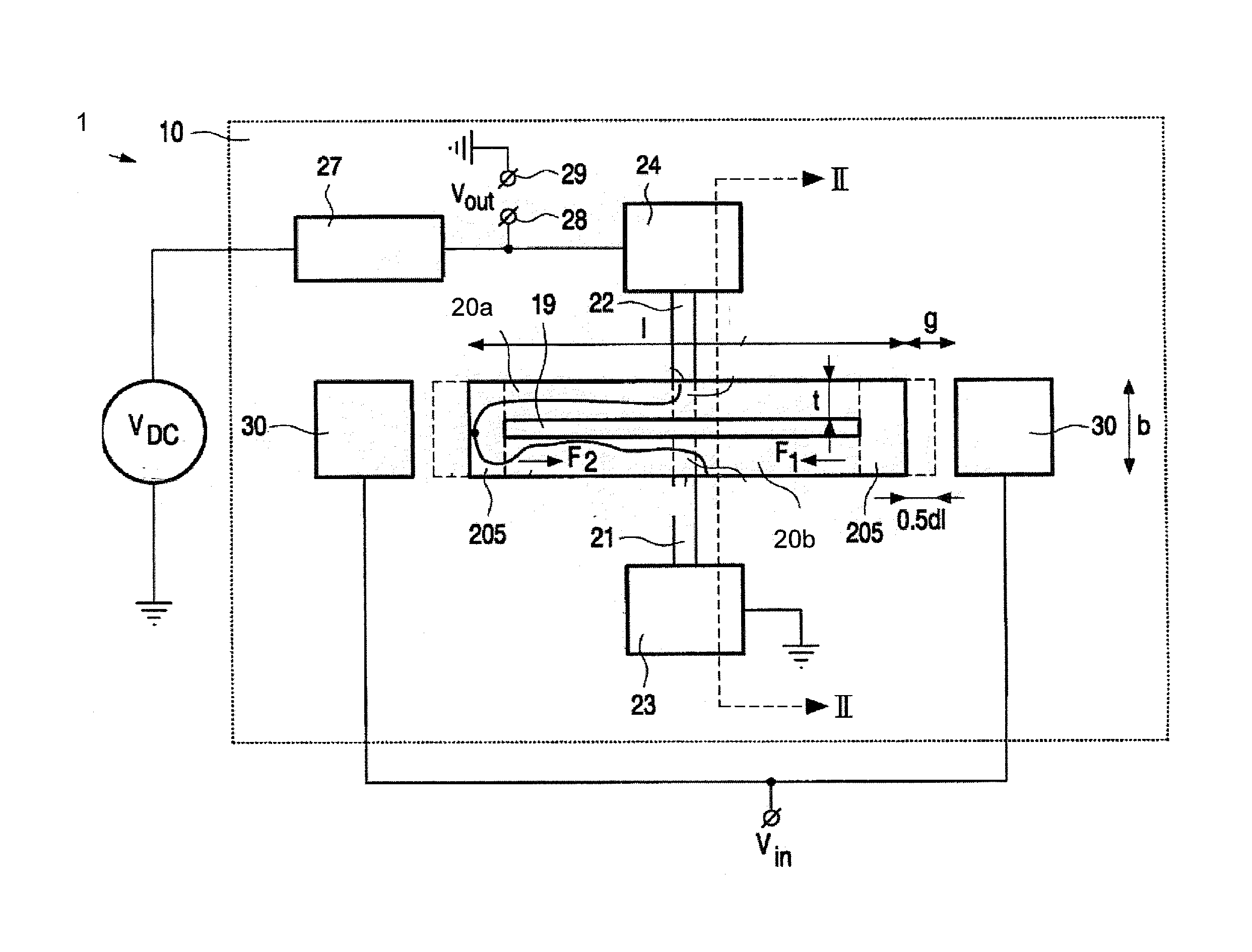
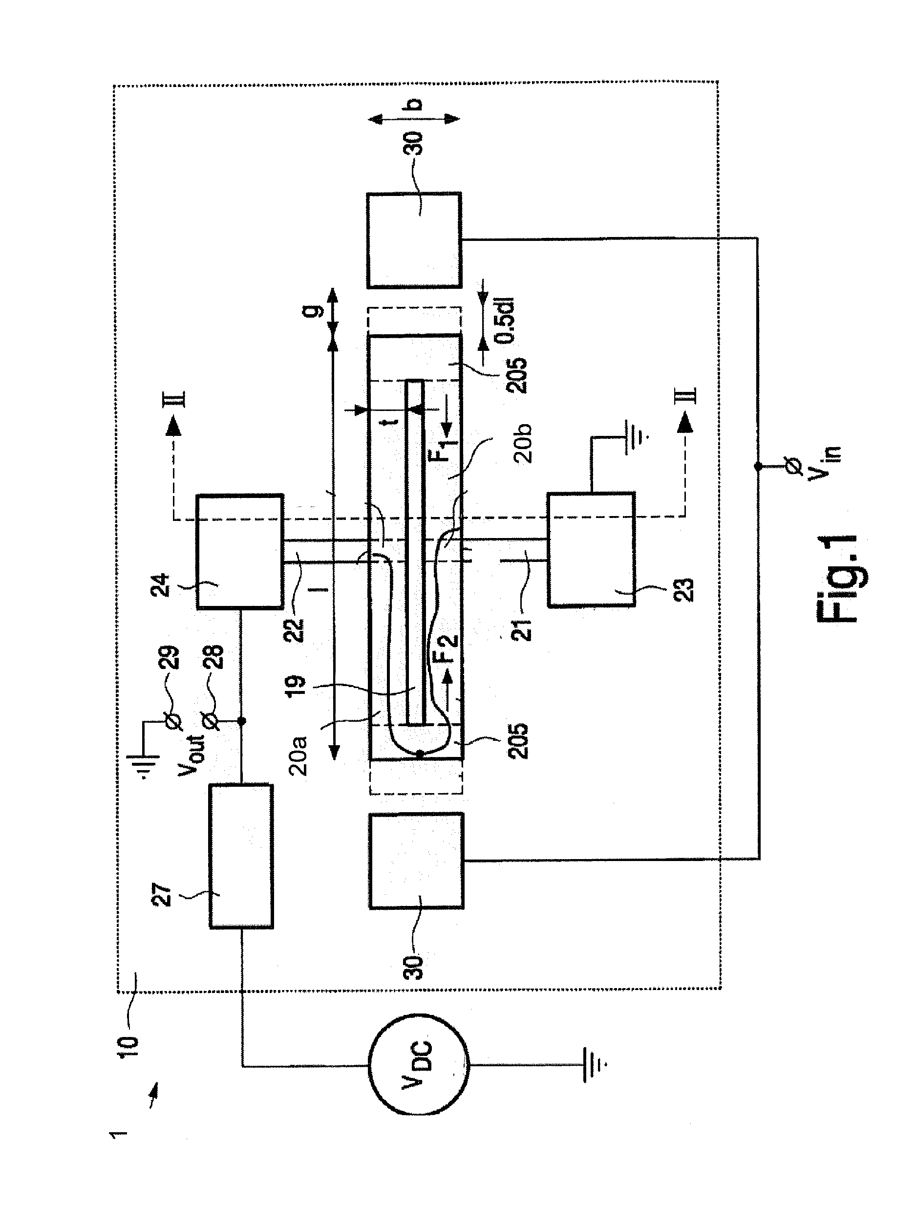
[0045]FIG. 1 shows a known piezoresistive MEMS resonator, which is described in more detail in WO 2004 / 053431.

[0046]The resonator 1 shown in FIG. 1 comprises a substrate 10 which is a silicon wafer. Alternatively, substrate 10 may be a gallium arsenide wafer or it may comprise any other semiconducting, metal or dielectric material. For resonators 1 designed for operation at frequencies above 10 MHz it is advantageous to use a substrate 10 comprising a dielectric such as, e. g., glass, because this reduces the loss of electromagnetic energy dissipated in the substrate.

[0047]The resonator 1 further comprises an electrically conductive resonator element 20 having two parallel connecting elements 20a, 20b. The resonator extends in a longitudinal direction having a length l, for operation in bulk mode. It is attached to the substrate 10 via support elements 21 and 22 which are connected to anchor elements 23 and 24, respectively. The anchor elements 23 and 24 are affixed to the substrate...


PUM


Abstract

A piezoresistive MEMS oscillator comprises a resonator body, first and second drive electrodes located adjacent the resonator body for providing an actuation signal; and at least a first sense electrode connected to a respective anchor point. The voltages at the electrodes are controlled and / or processed such that the feedthrough AC current from one drive electrode to the sense electrode is at least partially offset by the feedthrough AC current from the other drive electrode to the sense electrode.

Description

[0001]This application claims the priority under 35 U.S.C. §119 of European patent application no. 10172068.8, filed on Aug. 5, 2010, the contents of which are incorporated by reference herein.FIELD OF THE INVENTION[0002]This invention relates to MEMS oscillators, for example for generating clock signals or reference frequency signals.BACKGROUND OF THE INVENTION[0003]Electronic components inside flat objects, such as tags, bank cards or ID cards require a low profile of typically less than 0.5 mm. It is anticipated that flat, low-cost, and low power real time clocks (RTCs) and frequency reference oscillators (RFOs) are required residing inside these flat objects for future applications in the e-security, pharmaceutical, and food industry. An oscillator comprises a resonator and a feedback amplifier circuit, which are connected in a closed feedback loop. State-of-the-art RTCs make use of quartz crystal resonators with a height profile that typically exceeds the allowed sub-mm specifi...

Claims


Application Information

Patent Timeline
Patent Type & Authority Applications(United States)
IPC IPC(8): H03B5/30H02N1/08
CPCH03H9/02259
Inventor VERMEEREN, PETRUS ANTONIUS THOMAS MARINUSPHAN LE, KIM
Owner NXP BV
Why Eureka
Try Eureka