
Method for operating an automated guided, mobile assembly and/or material transport unit and automated guided, mobile assembly and/or material transport unit therefor

a technology of mobile assembly and/or material transportation, which is applied in the direction of steering control, non-vehicle mounted steering control, lifting device, etc., can solve the problems of no longer being used, poor energy efficiency, and not being able to use industrial trucks during this time, and achieves high energy density, high current, and high use time

Active Publication Date: 2012-02-16
BÄR AUTOMATION GMBH
View PDF12 Cites 3 Cited by
  • Summary
  • Abstract
  • Description
  • Claims
  • Application Information

AI Technical Summary

Benefits of technology

[0012]The present invention is furthermore based on the object or the technical problem of specifying a driverless, mobile assembly and / or material transport unit for use in the abovementioned method which enables a long use time, wherein a compact and light construction is intended to be provided and effective energy management can be used.
[0015]The driverless transport vehicle travels as far as a stop within its travel route. It stays for a short period of time for loading and unloading. During this time, it makes contact, via charging contacts, with an external charger, which is provided at the workstation, for example. The double-layer capacitor devices are charged with a high current during this time. With this energy, the transport vehicle can continue to travel for a certain amount of time until it arrives at a new charging station. Owing to the use of double-layer capacitor devices, a novel energy technology for driverless transport systems (DTS) or generally for battery-operated vehicles is possible.
[0016]Owing to the use of a double-layer capacitor device as energy store for the drive device of the assembly and / or material transport unit, it is possible to charge said double-layer capacitor device during the.residence time at an assembly station, with the result that very high use times are possible.
[0017]A particularly preferred configuration of the method according to the invention is characterized by the fact that an additional energy storage device with a high energy density, in particular a battery, is used, which in particular serves to ensure the ease of use of the driverless, mobile assembly and / or material transport unit in the event of relatively long standstill times. The volume and the weight of this battery can be markedly reduced, however, in comparison with the batteries used in the prior art since the energy for normal usage is provided by the double-layer capacitor device.
[0027]Since, during the use time, the energy for operating the driverless, mobile assembly and / or material transport unit is provided by the double-layer capacitor device, which is charged at the respective assembly station, the battery device can be in the form of a compact and relatively light battery device, as a result of which a compact and light construction of the driverless, mobile assembly and / or material transport unit is possible.
[0029]The considerable advantage of the boostcaps consists in that they can be charged and discharged almost as often as desired. This is also a considerable advantage in comparison with a battery which is spent after approximately 500 charge cycles. A further advantage is the use of double-layer capacitors owing to the low energy loss during the charging and discharging operations.

Problems solved by technology

It is not possible for the industrial trucks to be used during this time.
As soon as the state of charge of the batteries becomes critical, the assembly and / or material transport unit needs to be charged at a separate charging station and is no longer available for use purposes for a relatively long period of time.
Furthermore, induction-guided energy systems have the disadvantage that the floor needs to be cut open, there is a poor energy efficiency and the entire application is very expensive and inflexible.

Method used


Image

  • Method for operating an automated guided, mobile assembly and/or material transport unit and automated guided, mobile assembly and/or material transport unit therefor
  • Method for operating an automated guided, mobile assembly and/or material transport unit and automated guided, mobile assembly and/or material transport unit therefor
  • Method for operating an automated guided, mobile assembly and/or material transport unit and automated guided, mobile assembly and/or material transport unit therefor

Examples


Embodiment Construction

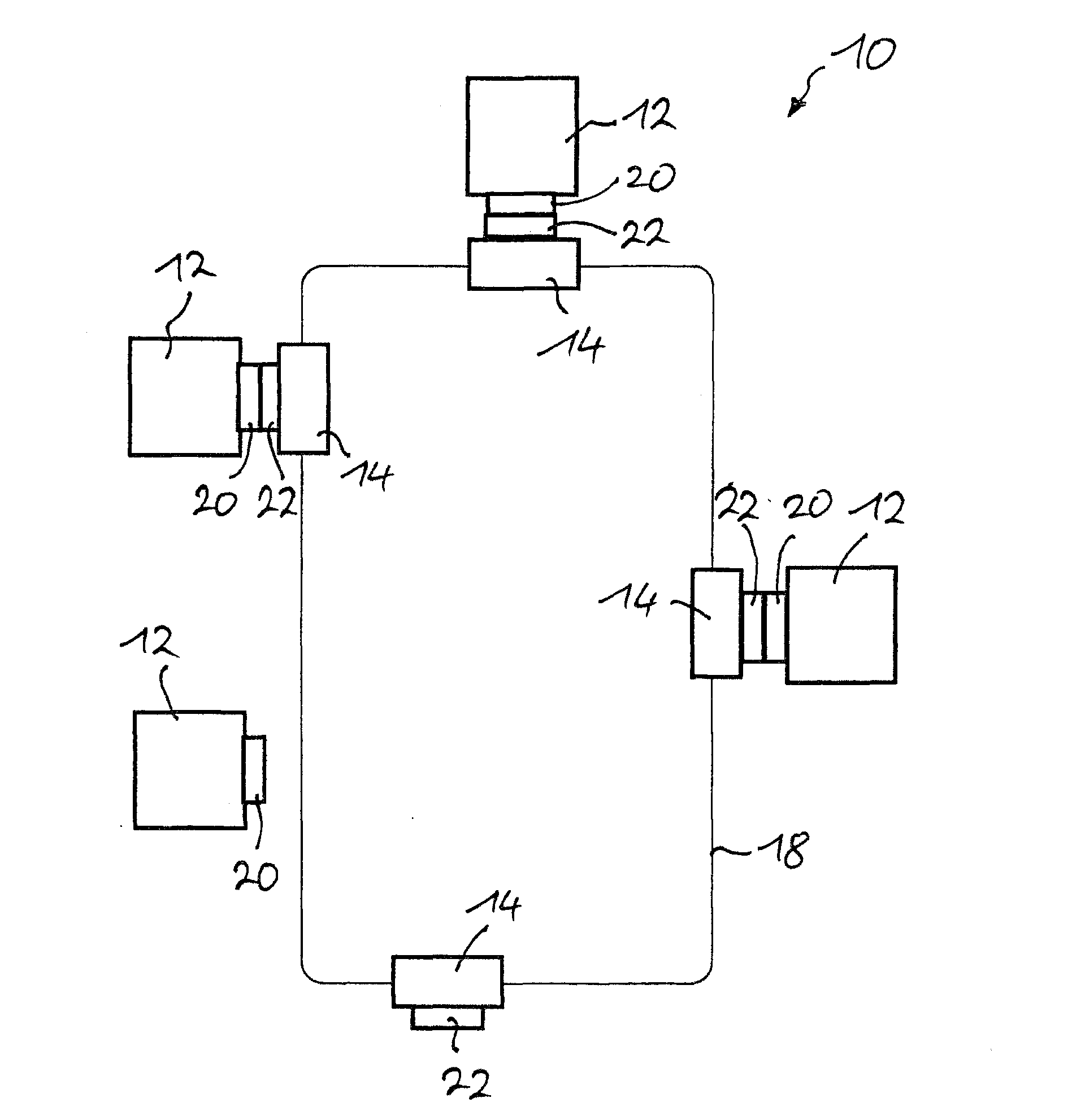
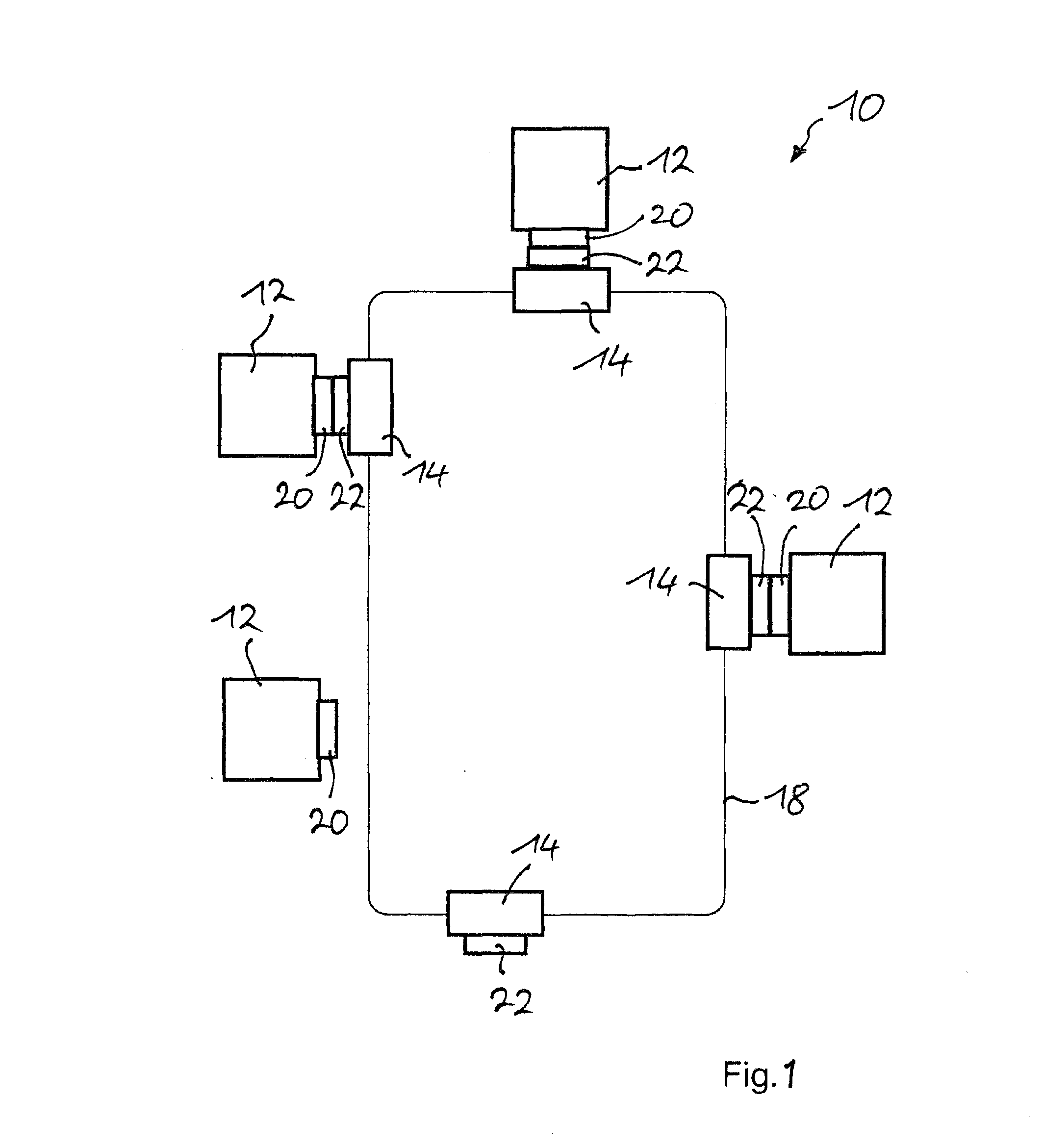
[0038]In the case of the assembly facility 10 illustrated in FIG. 1, fixed assembly stations 12 are provided which are driven up to by driverless, mobile assembly and / or material transport units 14.

[0039]In this case, a coded travel route 18 is provided between the individual assembly stations 12, said travel route being read by means of read units provided on the driverless, mobile assembly and / or material transport units 14 and being converted into a traveling movement via a control device. System control matches the traveling movements of the assembly and / or material transport units 14 to one another.

[0040]In addition to a coded travel route 18, it is also possible to perform respective positioning of the assembly and / or material transport units 14 via GPS (Global Positioning System) or optical or inductive control.

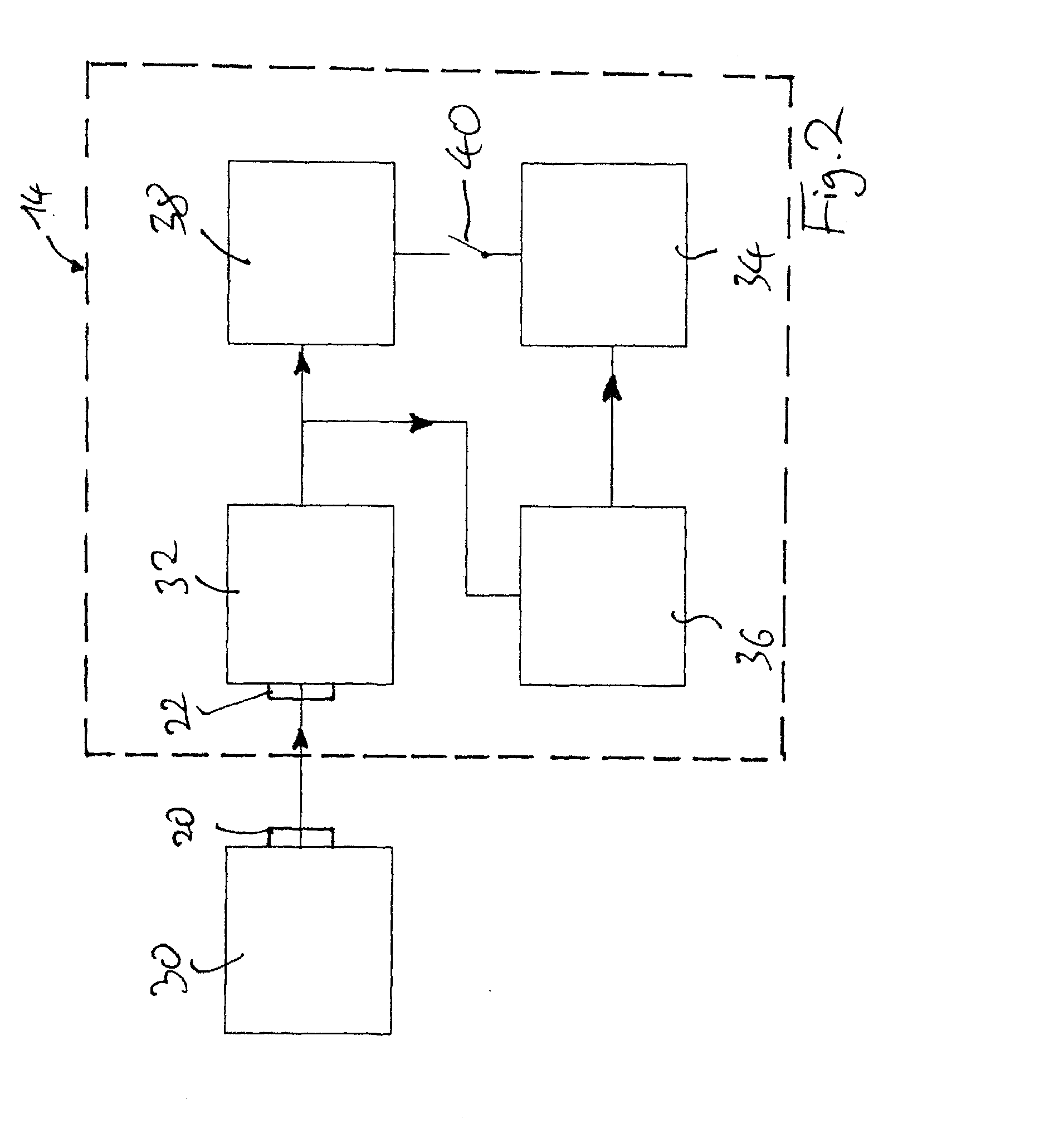
[0041]A double-layer capacitor device, i.e. an energy storage device which can be charged quickly, is used as the energy storage device for driving the drive device of...


PUM


Abstract

A method for operating a driverless, mobile assembly and / or material transport unit as a driverless transport system (DTS) with fixed assembly and / or warehousing stations. In this method, a system control device is used for the entire assembly process. The driverless, mobile assembly and / or material transport units comprises a travel device for the traveling movement of the unit, a drive device for the travel device,an energy storage device for providing the energy for the drive device and a control device for controlling the traveling movement in coordination with the system control device.

Description

CROSS-REFERENCE TO THE RELATED APPLICATION(S)[0001]This application is a U.S. National Phase Application under 35 U.S.C. §371 of International Patent Application No. PCT / DE2010 / 000430, filed Apr. 16, 2010, and claims the benefit of German Patent Application No. 102009017556.3, filed Apr. 17, 2009, all of which are incorporated by reference herein. The International Application was published in German on Oct. 21, 2010 as International Publication No. WO / 2010 / 118737 under PCT Article 21(2).FIELD OF THE INVENTION[0002]The present invention relates to a method for operating a driverless, mobile assembly and / or material transport unit as a driverless transport system (DTS) with fixed assembly and / or warehousing stations, wherein a system control device is used for the entire assembly process and the driverless, mobile assembly and / or material transport units have a travel device for the traveling movement of the unit, a drive device for the travel device, an energy storage device for pro...

Claims


Application Information

Patent Timeline
Patent Type & Authority Applications(United States)
IPC IPC(8): G05D1/02B60L50/15
CPCB60L15/38B60L53/32B60L2260/32B66F9/063Y02T10/7005Y02T10/7022Y02T10/7088Y02T90/121Y02T90/128Y02T90/14Y02T10/7072B60L53/11Y02P90/60B60L53/14B60L50/40B60L2200/44Y02T10/70Y02T90/12
Inventor BAR, RALF
Owner BÄR AUTOMATION GMBH
Learn More