Liquid crystal alignment process

a liquid crystal alignment and process technology, applied in the field of liquid crystal panel alignment process, can solve the problems of reducing the penetration rate, affecting the quality of images, and expensive equipment, so as to improve the efficiency of the exposure procedure, simplify the manufacturing process, and reduce the time to manufacture products

Inactive Publication Date: 2012-04-05
CHUNGHWA PICTURE TUBES LTD
View PDF19 Cites 12 Cited by
  • Summary
  • Abstract
  • Description
  • Claims
  • Application Information

AI Technical Summary

Benefits of technology

[0015]Compared to expose monomer materials by single-spectrum rays, the present invention does not need to substitute ultraviolet (UV) tubes and filters of different spectrums, and therefore is able to improve the efficiency of exposure procedure and reduce time to manufacture products since the mixed multi-spectrum rays are utilized to perform the exposure procedure for polymerizing the first monomer material and the second monomer material to form the first polymer alignment layer and the second polymer alignment layer. Moreover, the polymer alignment layers formed according to the present invention can maintain the quality of aligning the liquid crystal molecules. The liquid crystal molecules are aligned steadily and securely.
[0016]The present invention utilizes monomer materials to be polymerized to form structures for align...

Problems solved by technology

However, in the traditional MVA technology, the display aperture ratio is affected by the bumps 125, resulting in decrease of the penetration rate.
Moreover, the traditional MVA technology has drawbacks of dark fringes in a bright state and light leakage in a dark state, leading to degradation of the image quality.
The PI coating results in requirement of expensive equipments so that the manufacturing cost is hard to be cut down and reduced.
Moreover, the PI coating needs to use a PI cleaner, and hi...

Method used


Image

  • Liquid crystal alignment process
  • Liquid crystal alignment process
  • Liquid crystal alignment process

Examples


Embodiment Construction

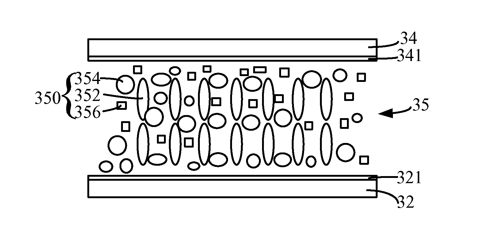
[0030]Please refer to FIGS. 3A to 3D which are diagrams showing a flow scheme of a liquid crystal alignment process implemented according to the present invention. As shown in FIG. 3A, a first substrate 32 and a second substrate 34 parallel to the first substrate 32 are provided. The first substrate 32 can be a thin-film transistor (TFT) array substrate. The second substrate 34 can be a substrate opposite to the TFT array substrate, or specifically, a color filter substrate (CF substrate). A first conductive layer 321 and a second conductive layer 341 are respectively disposed on the opposite surfaces of the first substrate 32 and the second substrate 34. The conductive layers 321 and 341 can be transparent indium tin oxide (ITO) films. A liquid crystal accommodating space 35 is formed between the first and second substrates 32 and 34, and more specifically, is formed between the first and second conductive layers 321 and 341.

[0031]As shown in FIG. 3A, a liquid crystal composition 3...


PUM


Abstract

A liquid crystal alignment process comprises steps of: providing a first substrate and a second substrate to form a liquid crystal accommodating space therebetween; pouring a liquid crystal composition into the liquid crystal accommodating space, the liquid crystal composition comprising liquid crystal molecules, a first monomer material, and a second monomer material; applying a voltage difference to the first and second substrates for arranging the liquid crystal molecules at a pre-tilt angle; and exposing the liquid crystal composition by mixed multi-spectrum rays for polymerizing the first monomer material and the second monomer material to form at least one type of liquid crystal alignment polymer on opposite surfaces of the first and second substrates. The liquid crystal alignment process is capable of improving the efficiency of exposure procedure, reducing time to manufacture products, and is capable of solving the problems of high costs and waste pollution.

Description

TECHNICAL FIELD OF THE INVENTION[0001]The present invention relates to a process for a liquid crystal panel, and more particularly, to a liquid crystal alignment process.BACKGROUND OF THE INVENTION[0002]Controlling the alignment of liquid crystal molecules is one of the most important technologies of manufacturing a liquid crystal display. The image quality of the liquid crystal display is related to the alignment of liquid crystal molecules. High-quality images can be presented only when the liquid crystal molecules are aligned steadily and uniformly in the display panel. A thin layer which is utilized for directionally arranging the liquid crystal molecules is generally called a liquid crystal alignment layer.[0003]According to different applications and principles, liquid crystal alignment technologies can be classified into a multi-domain vertical alignment (MVA) technology and a polymer sustained alignment (PSA) technology, for example.[0004]Taiwan Patent No. I325081 discloses ...

Claims


Application Information

Patent Timeline
IPC IPC(8): G02F1/1337G02F1/03
CPCC09K19/12C09K19/14C09K2019/0448G02F2202/02G02F2001/133715G02F2001/133765G02F2201/086G02F1/133788G02F1/133715G02F1/133765
Inventor SU, CHUN-WEILIEN, JAN-TIEN
Owner CHUNGHWA PICTURE TUBES LTD
Why Eureka
Try Eureka