Extreme ultraviolet light source apparatus
a light source and ultraviolet technology, applied in the field of extreme ultraviolet (euv) light source apparatus, can solve the problems of reducing the reflectance, damaging scattered debris damage the optical elements within the chamber, so as to achieve efficient capture, high efficiency, and efficient collection
- Summary
- Abstract
- Description
- Claims
- Application Information
AI Technical Summary
Benefits of technology
Problems solved by technology
Method used
Image
Examples
embodiment 1
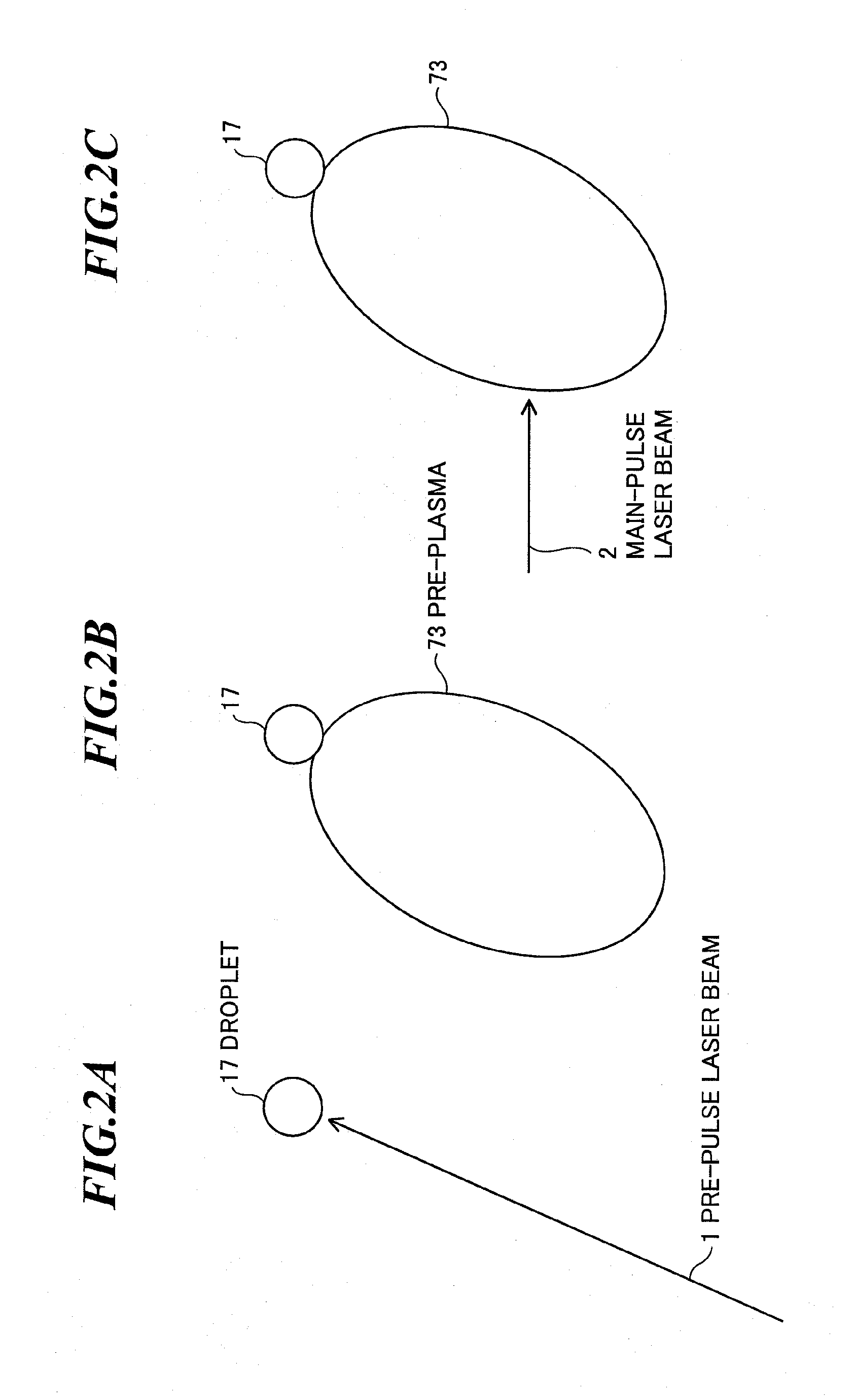
[0071]The first embodiment is an embodiment in a pre-pulse system (e.g., a pre-plasma system or a mass-limited target system) for expanding a target by using a pre-pulse laser beam, and then, irradiating the expanded target with a main-pulse laser beam.
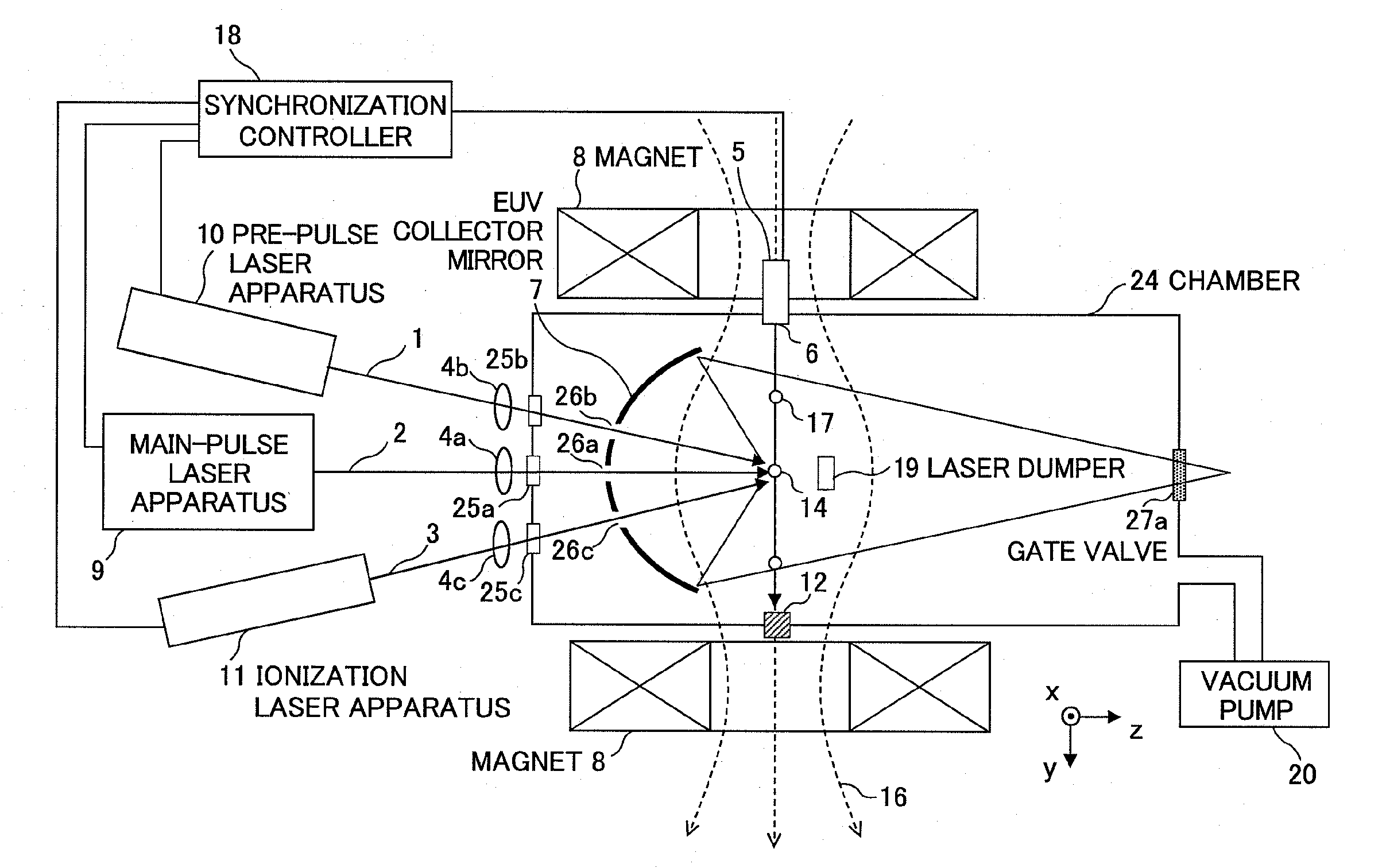
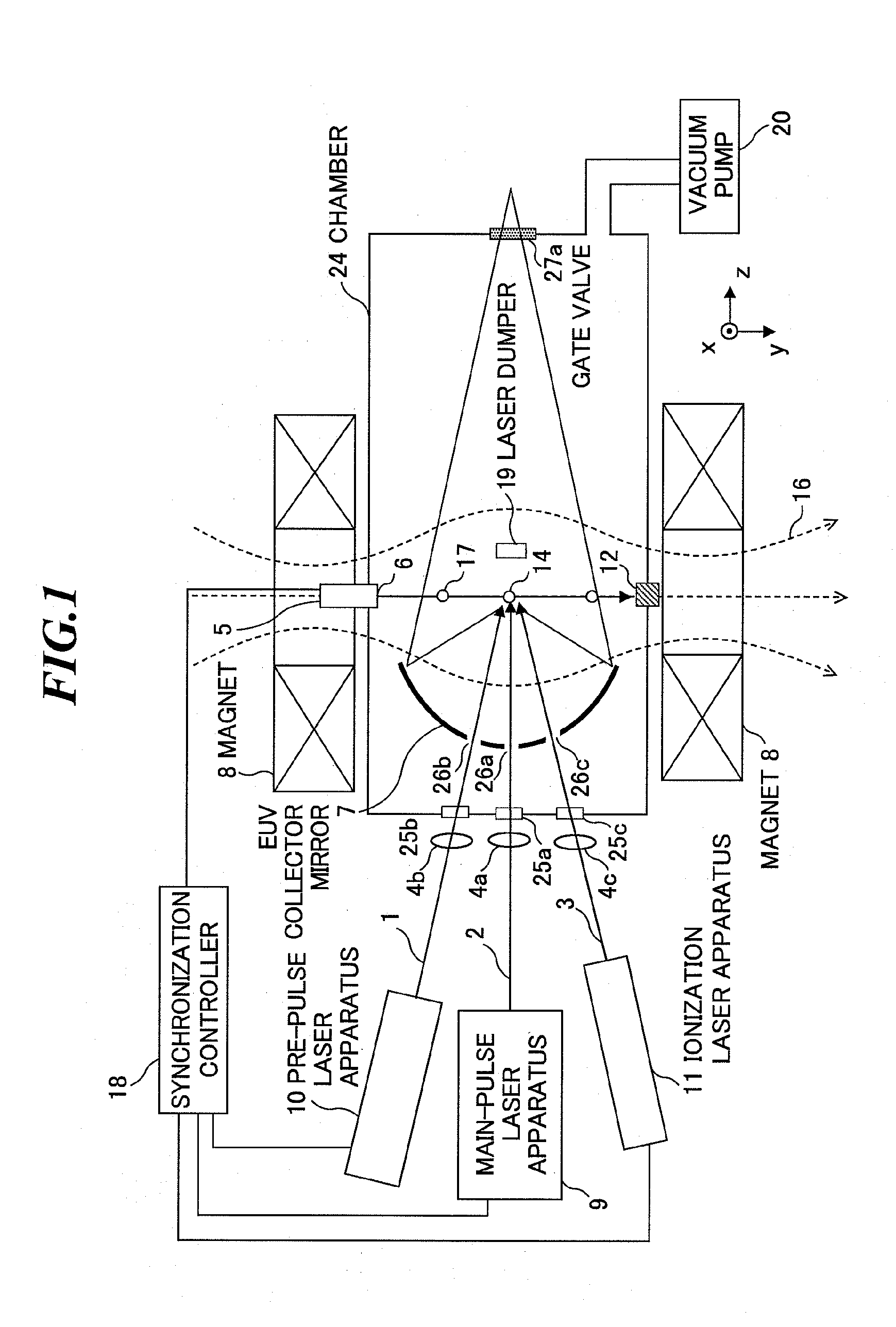
[0072]First, referring to FIG. 1, a basic configuration of an extreme ultraviolet (EUV) light source apparatus will be explained. FIG. 1 is a schematic diagram showing a configuration of an EUV light source apparatus according to the first embodiment of the present invention. The EUV light source apparatus employs a laser produced plasma (LPP) system for generating EUV light by irradiating a target with a laser beam to excite the target.
[0073]The EUV light source apparatus according to the first embodiment as shown in FIG. 1 includes a target supply unit 5, a main-pulse laser apparatus (a plasma generation laser unit for turning a target material into plasma) 9, a pre-pulse laser apparatus 10, an ionization laser apparatus (an ionizat...
embodiment 2
[0127]FIG. 8 is a schematic diagram showing a configuration of an EUV light source apparatus according to the second embodiment of the present invention, and FIG. 9 is a schematic diagram showing the EUV light source apparatus according to the embodiment seen from an output side of EUV light in a direction toward a light emission point.
[0128]As shown in FIG. 8, in the embodiment, the space near the plasma emission point 14 between the EUV collector mirror 7 and the plasma emission point 14 is irradiated with the ionization laser beam 3 as a sheet-shaped beam radiated in a direction orthogonal to the plain of paper of the drawing, and thereby, neutral particles moving toward the EUV collector mirror 7 are ionized to protect the EUV collector mirror 7. The sheet-shaped beam is created of a laser beam multiple-reflected as shown in FIGS. 10A and 10B, or a laser beam may be expanded to have a sheet shape by using a beam expander.
[0129]Further, as a mechanism of introducing the ionizatio...
embodiment 3
[0134]FIG. 11 is a schematic diagram showing a configuration of an EUV light source apparatus according to the third embodiment of the present invention, and FIGS. 12A and 12B show a relationship between a concave mirror and an ionization laser beam in the third embodiment.
[0135]As shown in FIG. 11, in the embodiment, a pair of concave mirrors 32 for multiple-reflecting an ionization laser beam is provided. As shown in FIGS. 12A and 12B, the pair of concave mirrors 32 are provided substantially symmetrically with respect to a line connecting the plasma emission point 14 and the center of the EUV collector mirror 7. The ionization laser beam 3 from the ionization laser apparatus (outside of the drawing) enters, for example, the rear surface of one concave mirror 32 from a direction as shown by an arrow in FIG. 12A. The ionization laser beam 3 is multiple-reflected between the pair of concave mirrors 32 and forms a conical beam, applied to a space near the plasma emission point 14 bet...
PUM
 Abstract
Description
Claims
Application Information
 - R&D
- Intellectual Property
- Life Sciences
- Materials
- Tech Scout
- Unparalleled Data Quality
- Higher Quality Content
- 60% Fewer Hallucinations
Browse by: Latest US Patents, China's latest patents, Technical Efficacy Thesaurus, Application Domain, Technology Topic, Popular Technical Reports.
© 2025 PatSnap. All rights reserved.Legal|Privacy policy|Modern Slavery Act Transparency Statement|Sitemap|About US| Contact US: help@patsnap.com


