Hybrid solar receiver and concentrating solar system comprising the same

a solar receiver and hybrid technology, applied in the direction of hybrid energy generation, indirect heat exchangers, lighting and heating apparatus, etc., can solve the problems of only viable solar photovoltaic projects, the service life of the cell is compromised, and the efficiency is obviously still low. , to achieve the effect of reducing the cost of solar photovoltaic projects

Inactive Publication Date: 2012-04-26
COMMISSARIAT A LENERGIE ATOMIQUE ET AUX ENERGIES ALTERNATIVES
View PDF14 Cites 26 Cited by
  • Summary
  • Abstract
  • Description
  • Claims
  • Application Information

AI Technical Summary

Benefits of technology

[0024]rapid thermal transfer. This makes it possible to control the temperature of the photovoltaic cells.
[0025]In other words, the invention is applicable to a process that has a source of intense heat, due to the concentration of solar energy by solar concentrators, and has relatively fine photovoltaic cells (typically from 100 to 180 μm). The cells are also very fragile because of differential expansion caused by differences in temperature at various points on the surface of the cell. In conventional devices, this phenomenon quickly causes material fatigue which results in the material failing. In fact, if the temperature difference on a photovoltaic cell exceeds 5° C., the service life of the cell is compromised. Consequently, the invention makes it possible to obtain greater temperature homogeneity on the cells and this increases their service life and operational stability.

Problems solved by technology

This efficiency is obviously still low and the price of the electricity produced is still higher than that of electricity produced using traditional methods—this often means that solar photovoltaic projects are only viable because they are subsidised.
However, the drawback is that the flow of gas used to extract the heat may not remove accumulated heat from the photovoltaic panel fast enough or sufficiently and overall efficiency is therefore not high and this limits the use of the system.
Nevertheless, this system is the result of simply superposing a conventional photovoltaic panel and a heat pipe: the dissipation of heat from the photovoltaic panel is not optimised due to the high thermal resistance of the rear face of the photovoltaic panel which is formed by a layer of a copolymer of ethylene-vinyl acetate (referred to hereafter as “EVA”) and a co-laminated layer of polyvinyl fluoride (PVF) and polyethylene terephthalate marketed under the brand name “TEDLAR®”.
In addition, the meandering hole in the heat pipe is provided in order to increase the heat exchange surface but this structure limits the circulation of the heat transfer fluid through the heat pipe.
Such a system can only function at low solar intensity levels because when the solar intensity is high, the meandering hole prevents circulation of the heat transfer fluid towards the condenser and, ultimately, the heat pipe cannot operate correctly.
Finally, with a 2-plate structure that has a meandering hole, the heat exchange surface of the heat pipe is independent of the surface of the photovoltaic cells and there is a risk that the temperature on the surface of the photovoltaic cells will not be homogeneous.
The current problem with hybrid solar thermal / electricity receivers is that there is a conflict between the average effective temperature of the photovoltaic cells and that of the thermal receiver.
Because of the relatively low intensity of the sun's rays and the low efficiency of photovoltaic cells (approximately 15%), if one increases the average temperature of the photovoltaic cells in an attempt to recover high-temperature thermal energy, the peak power of the photovoltaic cells drops sharply (0.4% / ° C.) and generating efficiency is even more adversely affected.
To sum up, hybrid solar photovoltaic electricity / heat receivers are juxtaposed devices that do not make it possible to optimise the simultaneous generation of electricity and heat using solar radiation.
However, concentration results in a very significant increase in the temperature of the photovoltaic cell, to the extent that the efficiency of the cells is only around 15% and 85% of the solar radiation is dissipated as heat.
A system like this has many disadvantages: firstly, the photovoltaic cells are not protected against the air and humidity and can therefore corrode; moreover, given that the solar radiation is concentrated, the electrical current produced is high and there is a risk of electrical conduction between the cells and the heat pipe because the intermediate layers are only thermal conductivity layers and metallic layers (electrically conductive); then, the intermediate layers are mechanically attached to the heat pipe by an elastic plate and this poses a mechanical problem on the photovoltaic cells because there is a risk of the photovoltaic cells being crushed by the differential force produced by a non-uniform temperature; finally, this system is only used to cool the cells using air with a considerable heat exchange surface and cannot produce a warm liquid coolant.

Method used


Image

  • Hybrid solar receiver and concentrating solar system comprising the same
  • Hybrid solar receiver and concentrating solar system comprising the same
  • Hybrid solar receiver and concentrating solar system comprising the same

Examples


second embodiment

[0106]FIG. 4a shows a second embodiment with a heat pipe having a rectangular cross-section. Heat discharge area (3a) has four planar surfaces and surface S2 is placed on and in contact with one of the four planar surfaces of heat discharge area (3a) of said heat pipe (3) via layer (4).

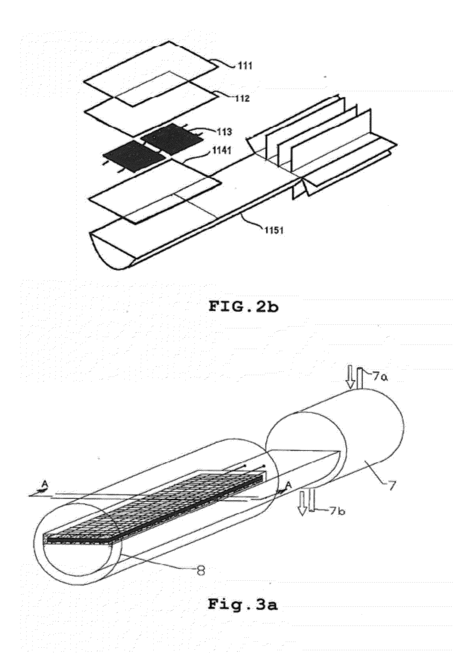
[0107]FIG. 4b shows a cross-section along line A-A in FIG. 4a. The internal structure of the heat pipe can have grooves acting as a capillary structure but it can also have other capillary structures (not shown) that make it possible to drain the thermal flux in order to make heat transfer more intense.

third embodiment

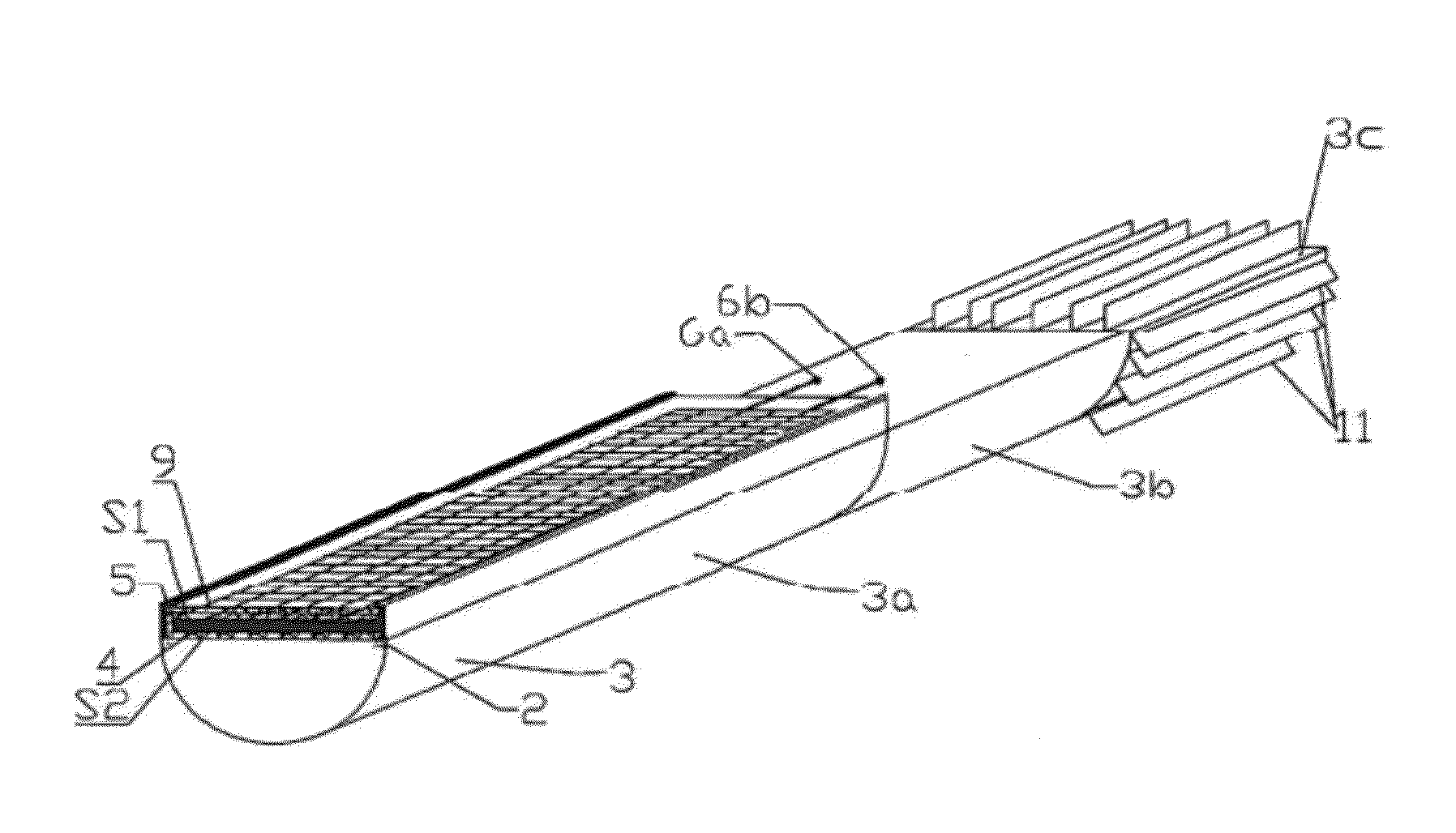
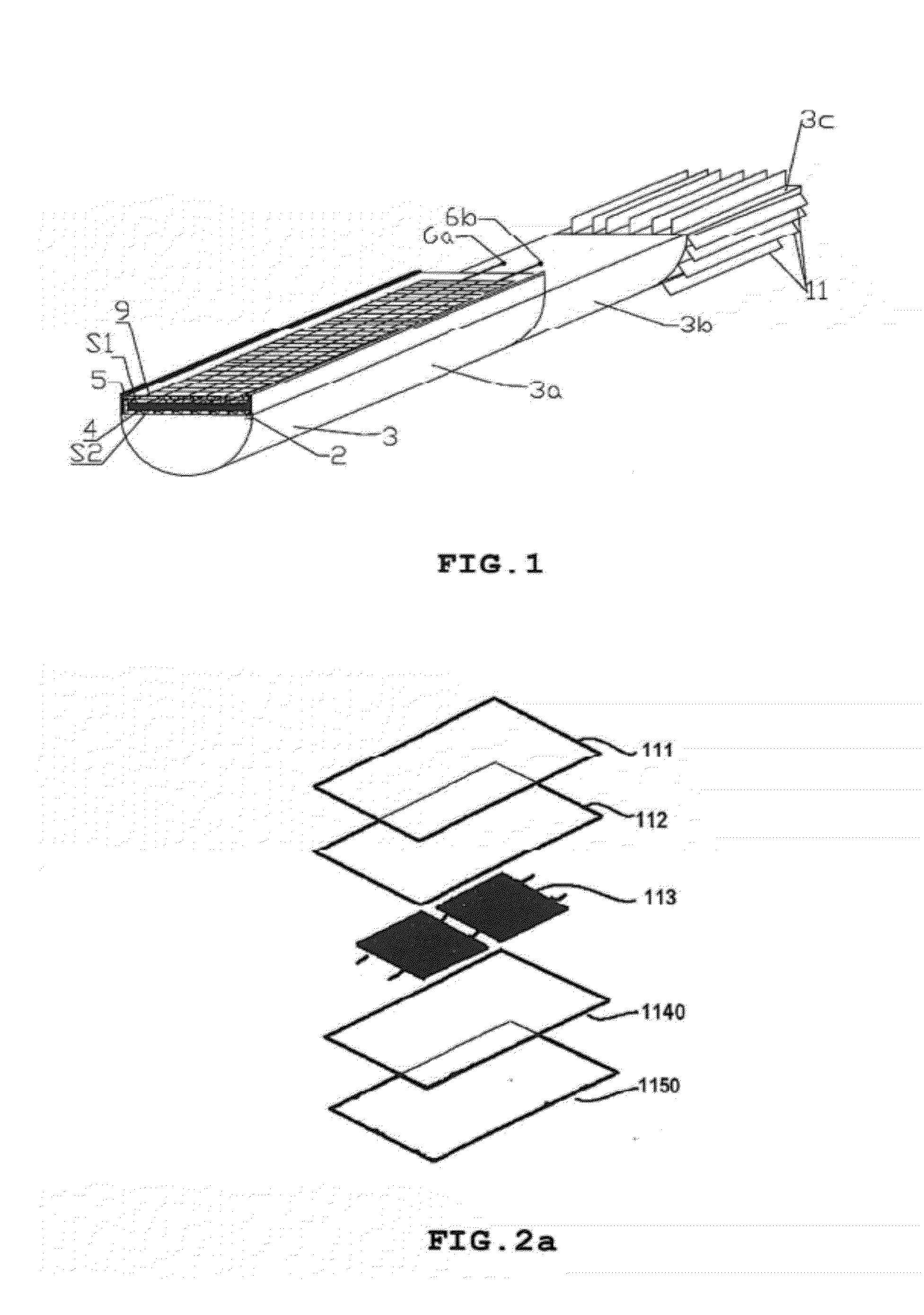
[0108]FIG. 5a shows a third embodiment with a heat pipe having a circular cross-section. Heat discharge area (3a) is a cylinder and surface S2 is placed on and in contact with the cylindrical surface of heat discharge area (3a) via layer (4).

[0109]FIG. 5b shows a cross-section along line A-A in FIG. 5a. The internal structure of said heat pipe can have grooves acting as a capillary structure but it can also have other capillary structures (not shown) that make it possible to drain the thermal flux in order to make heat transfer more intense.

[0110]FIG. 6a shows another embodiment with a heat pipe having a circular cross-section and fins. Heat discharge area (3a) is a cylinder with one fin on each side of the tube. Surface (S2) is placed on and in contact with the cylindrical surface of heat discharge area (3a) via layer (4). Surface (S2) can be placed on and in contact with said fins. FIG. 6b shows a cross-section along line A-A in FIG. 6a. The internal structure of the heat pipe can...


PUM


Abstract

The object of the hybrid solar receiver according to the invention is to generate electricity and heat simultaneously in an optimum manner.
It comprises photovoltaic cells (2) for converting the sun's rays concentrated on the cells into electricity and a heat pipe (3) in order to discharge the heat accumulated on photovoltaic cells (2) via a liquid coolant. Heat pipe (3) has a heat discharge area (3a) that serves as an evaporator for discharging the heat accumulated on the photovoltaic cells (2) and a dissipation area (3c) for dissipating the heat that it absorbs, the entire rear face (S2) of photovoltaic cells (2) being placed on and in contact with heat discharge area (3a) of heat pipe (3) via a dual-function interface layer (4) that electrically insulates the photovoltaic cells (2) from the heat pipe (3) in order to instantaneously transfer the heat accumulated on photovoltaic cells (2) to the liquid coolant in the heat pipe. The entire surface of photovoltaic cells (2), except for the rear surface (S2), is coated with a layer (5) of an encapsulation product and a transparent plate (9) is deposited on layer (5).
Using such a receiver with a linear concentrator forms a concentrating solar system that generates electricity and heat for domestic use in an optimum manner.

Description

SUMMARY OF THE INVENTION[0001]The present invention relates to a hybrid (photovoltaic and thermal) solar receiver designed to generate electricity and heat simultaneously by optimising the surface area of the photovoltaic cells used and which is especially suitable for domestic use.BACKGROUND OF THE INVENTION[0002]Against the background of economic growth, the energy sector must, on an international scale, keep pace with increasing demand for energy despite increasingly scarce resources whilst also responding to the dangers of climate change caused by the emission of greenhouse gases. Changes in the technologies that are used and the shift from conventional to renewable energy sources will obviously depend on the kilowatt hour price of the energy produced.[0003]Nowadays, with on-going improvements being made, the efficiency of solar photovoltaic panels is roughly 15%. This efficiency is obviously still low and the price of the electricity produced is still higher than that of electr...

Claims


Application Information

Patent Timeline
Patent Type & Authority Applications(United States)
IPC IPC(8): H01L31/058H01L31/052F24S10/40F24S20/20F24S23/00
CPCF24J2/06H01L31/0547F28D15/0233F28D15/0275F28D15/04Y02B10/10Y02B10/20Y02B10/70Y02E10/41Y02E10/44Y02E10/52Y02E10/60F28D21/0001H01L31/054H02S40/44F24J2/07F24S23/00F24S20/20F24S50/20Y02E10/47Y02E10/40
Inventor LIN, QINGLONGMANIFICAT, ANDRE
Owner COMMISSARIAT A LENERGIE ATOMIQUE ET AUX ENERGIES ALTERNATIVES
Why Eureka
Try Eureka