
Microfluidic Chip Capable of Synthesizing Radioactively Labeled Molecules on a Scale Suitable for Human Imaging With Positron Emission Tomography

a radioactive labeled molecule and microfluidic chip technology, applied in nuclear engineering, nuclear elements, transportation and packaging, etc., can solve the problems of difficult modification of modules and reactors for the research and development of new compounds and probes, large space occupation of modules or reactors, and long reaction time cycles of chemical processes. achieve the effect of faster and more efficien

Inactive Publication Date: 2012-04-26
SIEMENS MEDICAL SOLUTIONS USA INC
View PDF1 Cites 25 Cited by
  • Summary
  • Abstract
  • Description
  • Claims
  • Application Information

AI Technical Summary

Benefits of technology

[0011]In one embodiment, the microfluidic devices disclosed in the present application allow the efficient processing of chemical reactions in a microscale. In one particular aspect, the microfluidic devices allow the synthesis of F-18-labeled molecules for PET imaging in an efficient and compact manner, and also allow the process to be performed in a short period of time. The microfluidic devices are designed as a universal devices; that is, they are readily modifiable devices suitable for the preparation of many known molecular probes as well as development of new probes.
[0013]As disclosed herein, the microfluidic device or chip of the present application is capable of processing and labeling substrates within 5 minutes on a scale leading to several human doses (100 mCi). This scale constitute over 1000 times difference in output compared with the prior chip known in the art. The microfluidic device is also faster and more efficient than any known macroscale synthesizers.
[0016]A number of synthesizers known in the art employ pressure actuated elastomeric valves or pneumatic valves. In addition, there is significant literature disclosing the control of microfluidic valves by various methods of actuation. See for example, US 20020127736. However, under standard reaction processing conditions, the pneumatic valves are pushed to the limit of operation by the internal vapor pressures that are generated during various processing steps, such as a solvent evaporation steps. In one particular embodiment, the microfluidic device disclosed in the present application employs pneumatic valves that are capable of operating efficiently under high pressures. The design of the microfluidic device disclosed herein accomplishes these and other objectives as disclosed herein.
[0018]In one particular embodiment, the microfluidic device comprises an integrated chemical reaction circuit (CRC or “chip”). The CRC of the present application provides a number of new and useful features that overcome the limitations that are associated with the current microfluidic chips. In certain embodiments, the chip comprises a novel reaction chamber (or reactor) design. In one aspect, the chip comprises a mixer for effectively mixing reagents and solvents in the reaction chamber.

Problems solved by technology

Such modules or reactors occupy a large amount of space and the chemical process requires longer reaction time cycles than desired for the preparation of the labeled compounds.
These modules and reactors are also difficult to modify for the research and development of new compounds and probes.
But their main drawback is that the reactions take place with reduced efficiency arising from tremendous dilution of reagents necessary only for macroscopic liquid handling.
However, the design and configuration of this microfluidic chip have certain limitations, and the chip does not permit the preparation of the labeled product on a significantly larger scale.
Inevitably, a considerable decrease in the radiochemical yields of the resulting probe are obtained from these commercial synthesizers because of the long processing times, low reagent concentrations and the short half-life of [F-18]fluorine (t1 / 2=109.7 min).
Moreover, because the commercialized automation system is constructed for macroscopic synthesis, the process requires the consumption of large amount of valuable reagents (e.g. mannose triflate), which is inefficient and wasteful for performing research at the smaller scale.
However, the design of this microfluidic chip is such that it is not capable of scaling up by over a 1500 fold that is required to achieve a desired 100 mCi level of activity.
In addition, the particular design of the reaction process does not permit a significant increase in the output or the yield.
In addition to the inability to scale up the UCLA microfluidic chip, the inherent design of the chip also limits the loading of reagent activity thereby limiting the reaction throughput.
That is, the microfluidic chip requires over 1 hour to load a minimal (500 microcuries) activity onto the exchange resin, which is an unacceptable period of processing time given the short half-life of F-18.

Method used


Image

  • Microfluidic Chip Capable of Synthesizing Radioactively Labeled Molecules on a Scale Suitable for Human Imaging With Positron Emission Tomography
  • Microfluidic Chip Capable of Synthesizing Radioactively Labeled Molecules on a Scale Suitable for Human Imaging With Positron Emission Tomography
  • Microfluidic Chip Capable of Synthesizing Radioactively Labeled Molecules on a Scale Suitable for Human Imaging With Positron Emission Tomography

Examples


Embodiment Construction

[0033]Compared to known or commercial microfluidic chips, the microfluidic device of the present application comprises of a number of novel elements and components, and their various combinations. Certain elements and components and non-limiting design configuration of the microfluidic device is illustrated below:

1) Ion Exchange Column:

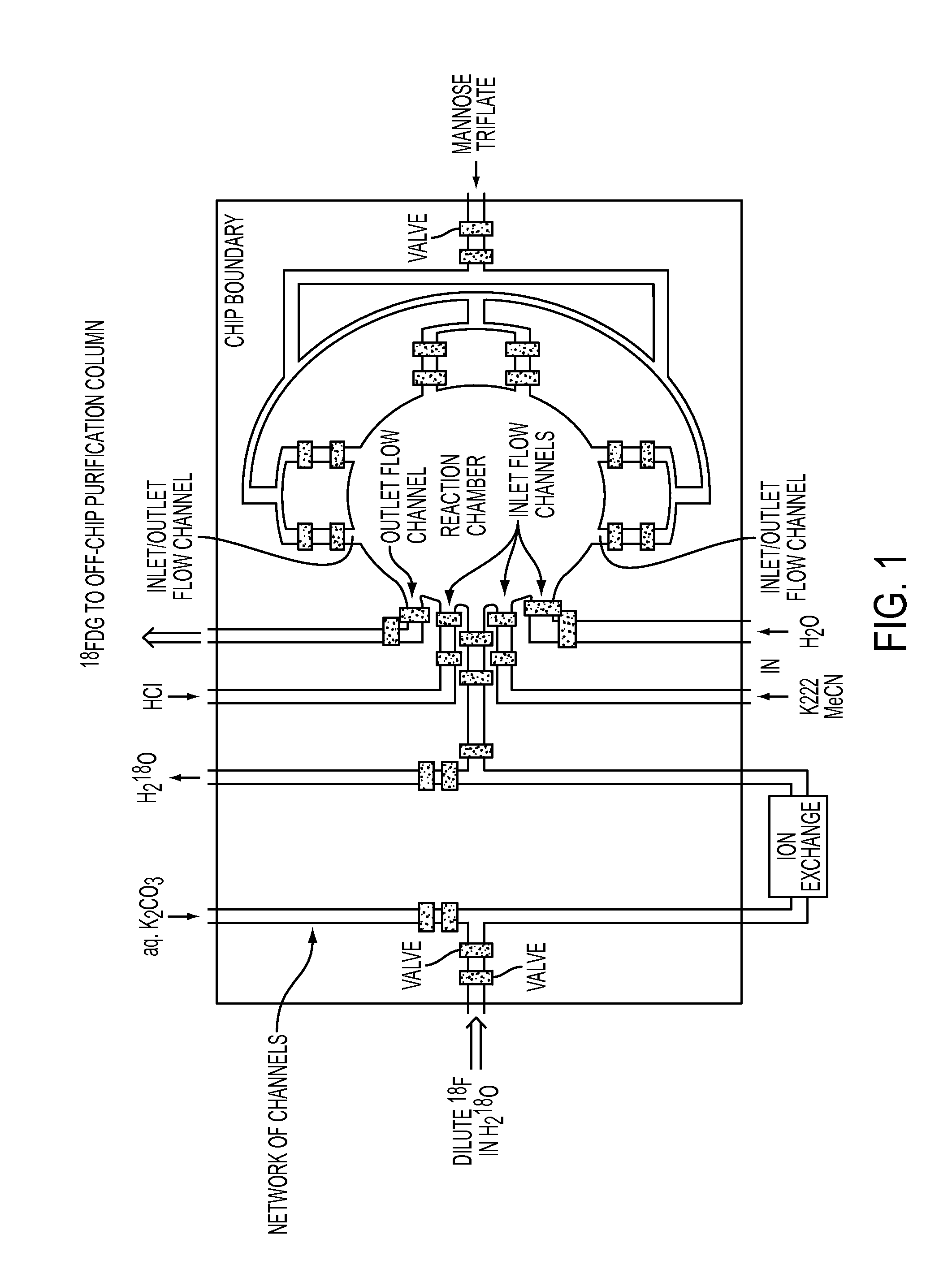
[0034]The current, known FDG chip design presents a number of scale-up challenges. For example, the currently available FDG chip contains an on-chip ion exchange column that is capable to trapping several orders of magnitude less activity than required for certain applications; that is, about 60 microCi as compared to a target of 300 milliCi. It is unlikely that this scaling issue can be resolved with an on-chip nanoscale columns, since it would require as many as 5,000 parallel columns to trap sufficient amounts of fluoride to meet the desired activity.

[0035]In addition, the processing throughput of the known microfluidic chips is also limited. Curr...


PUM


Abstract

Described herein are automated, integrated microfluidic device comprising a chemical reaction chip comprising for performing chemical reaction, a microscale column integrated with the chip and configured for liquid flow from the column to at least one flow channel, and wherein the fluid flow into the column is controlled by on-chip valves; and comprising at least two on-chip valves for controlling fluid flow in the microfluidic device.

Description

FIELD OF THE INVENTION[0001]The present inventions relate to microfluidic devices and related technologies, and chemical processes using the devices. More specifically, the application also discloses the synthesis of radioactive compounds for imaging, such as by PET, in a fast, efficient and compact manner.BACKGROUND OF THE INVENTION[0002]Large-scale synthesis modules have been developed and used for the preparation of a number of radiopharmaceutical compounds, including 2-deoxy-2-[F-18]-fluoro-D-glucose (FDG) and 3′-deoxy-3′-[F-18]-fluorothymidine (FLT). Such modules or reactors occupy a large amount of space and the chemical process requires longer reaction time cycles than desired for the preparation of the labeled compounds. These modules and reactors are also difficult to modify for the research and development of new compounds and probes. But their main drawback is that the reactions take place with reduced efficiency arising from tremendous dilution of reagents necessary only...

Claims


Application Information

Patent Timeline
Patent Type & Authority Applications(United States)
IPC IPC(8): C07H21/00C08B37/00G21C1/00
CPCB01F11/0042B01J2219/00986B01F13/0059B01J19/0093B01J2219/00286B01J2219/00396B01J2219/00398B01J2219/00414B01J2219/00418B01J2219/00495B01J2219/00585B01J2219/00599B01J2219/00731B01J2219/00759B01J2219/00783B01J2219/00788B01J2219/00822B01J2219/00824B01J2219/00826B01J2219/00828B01J2219/00831B01J2219/00833B01J2219/00858B01J2219/0086B01J2219/00862B01J2219/00873B01J2219/00889B01J2219/00891B01J2219/00907B01J2219/00916B01J2219/00927B01F11/0071B01F31/29B01F31/65B01F33/30B01J19/00B81B7/00B81C1/00
Inventor ELIZAROV, ARKADIJ M.KOLB, HARTMUTH C.VAN DAM, R. MICHAELHEATH, JAMES R.
Owner SIEMENS MEDICAL SOLUTIONS USA INC
Learn More