Amplification optical fiber and optical fiber amplifier and resonator using the same

a technology of optical fiber and amplifier, applied in the direction of cladded optical fibre, instruments, optical elements, etc., can solve the problems of reducing the gain of lp01 mode, unable to obtain sufficient output, and reducing the beam quality of output light, so as to achieve good beam quality and good beam quality

Active Publication Date: 2012-05-03
THE FUJIKURA CABLE WORKS LTD
View PDF2 Cites 13 Cited by
  • Summary
  • Abstract
  • Description
  • Claims
  • Application Information

AI Technical Summary

Benefits of technology

[0035]According to the resonator, in the resonance of light, when light propagates through the core of the amplification optical fiber, the LP01 mode is amplified higher than the LP02 mode and the LP03 mode. Therefore, in comparison with a case of using a fiber in which the active element is added to the core at a uniform concentration, it is possible to output light with a good beam ...

Problems solved by technology

The existence of the higher-order mode reduces the beam quality of output light and, for example, the output light is less likely to be collected.
However, since an ...

Method used


Image

  • Amplification optical fiber and optical fiber amplifier and resonator using the same
  • Amplification optical fiber and optical fiber amplifier and resonator using the same
  • Amplification optical fiber and optical fiber amplifier and resonator using the same

Examples


first embodiment

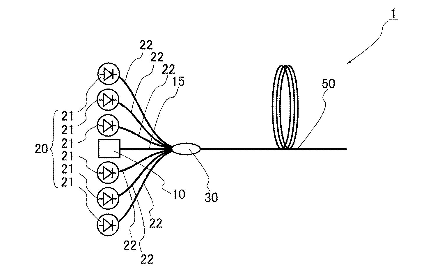
[0048]FIG. 1 is a view showing an optical fiber amplifier according to a first embodiment of the invention.

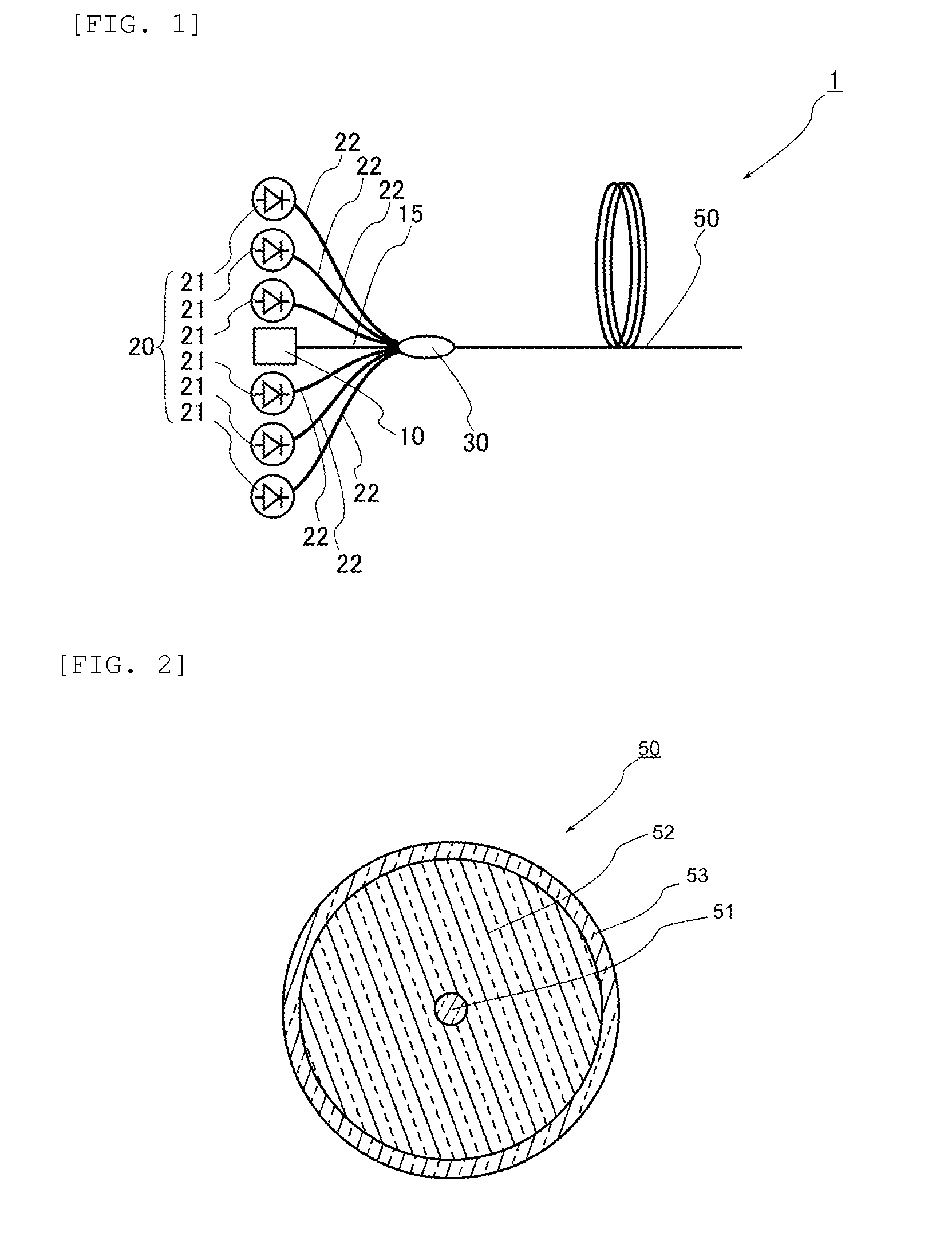
[0049]As shown in FIG. 1, an optical fiber amplifier 1 in this embodiment mainly includes a seed light source 10 outputting light as seed light, a pumping light source 20 outputting pumping light, an optical combiner 30 to which the seed light and the pumping light are input, and an amplification optical fiber 50. The seed light and the pumping light output from the optical combiner 30 are input to the amplification optical fiber 50, and an active element pumped by the pumping light is added to the amplification optical fiber 50.

[0050]The seed light source 10 is constituted of, for example, a semiconductor laser device and a Fabry-Perot type or fibering type fiber laser device. The seed light source 10 is configured to output light including an LP01 mode from an optical fiber. Although the seed light output from the seed light source 10 is not limited especially as long as it i...

second embodiment

[0077]Next, a second embodiment of the invention will be described in detail with reference to FIG. 4. The components same as or corresponding to those of the first embodiment are assigned the same reference numerals except for the cases to be described especially, and overlapping descriptions thereof are omitted. FIG. 4 is a view showing a state of a core of an amplification optical fiber according to the second embodiment of the invention and corresponds to FIG. 3 of the first embodiment.

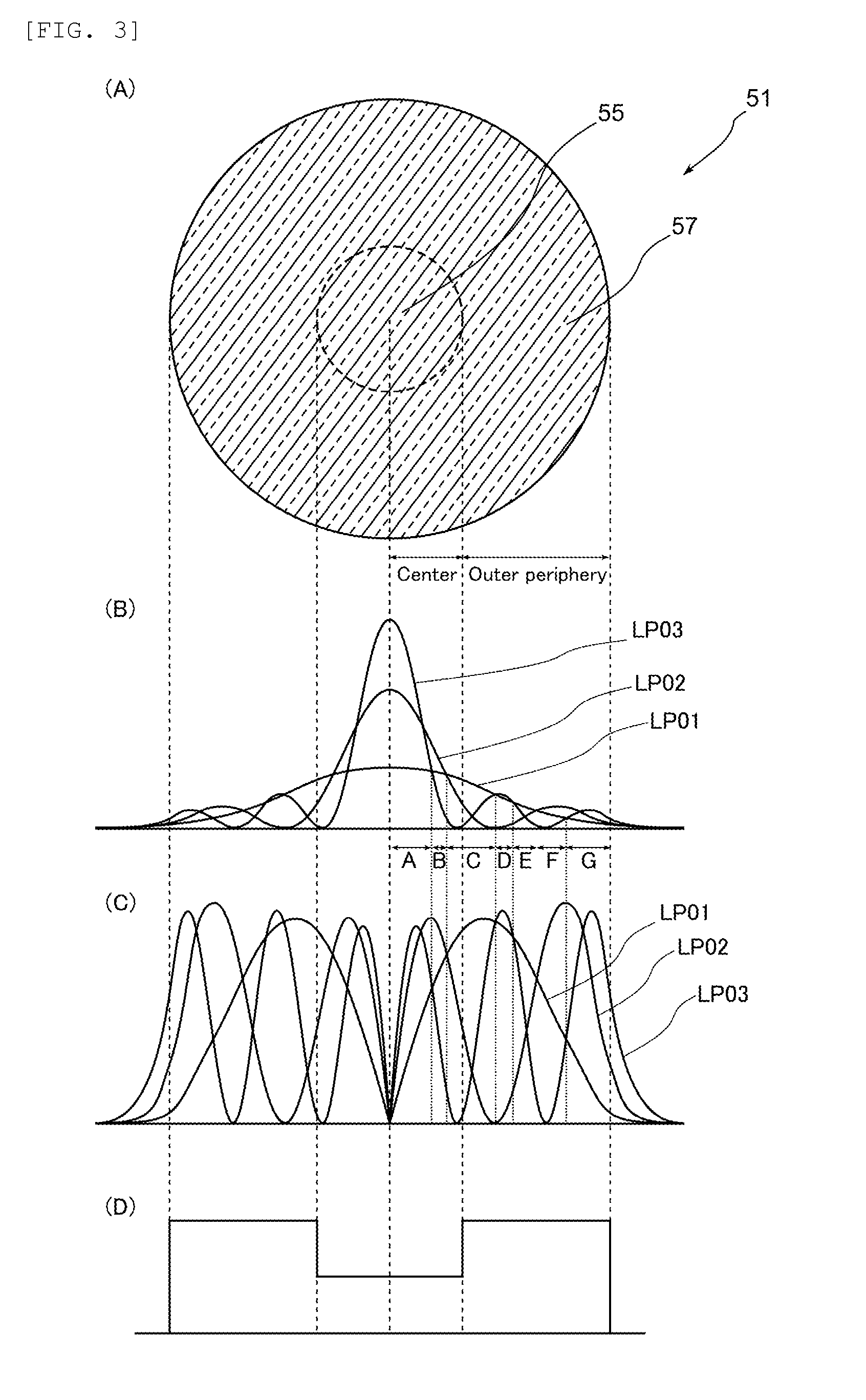
[0078]As shown in FIG. 4A, the amplification optical fiber in this embodiment uses a core 51a instead of the core 51 of the amplification optical fiber 50 of the first embodiment. The core 51a is separated into a center region 55a and an outer peripheral region 57a as with the core 51 of the first embodiment separated into the center region 55 and the outer peripheral region 57. As shown in FIG. 4D, an active element is added to the outer peripheral region 57a at a concentration similar to the out...

third embodiment

[0081]Next, the third embodiment of the invention will be described in detail with reference to FIG. 5. The components same as or corresponding to those of the first embodiment are assigned the same reference numerals, and overlapping descriptions thereof are omitted except for the cases to be described especially. FIG. 5 is a view showing a state of a core of an amplification optical fiber according to the third embodiment of the invention and corresponds to FIG. 3 of the first embodiment.

[0082]As shown in FIG. 5A, the amplification optical fiber in this embodiment uses a core 51b instead of the core 51 of the amplification optical fiber 50 of the first embodiment. While the core 51 of the first embodiment is separated into the center region 55 and the outer peripheral region 57, the core 51b has an intermediate region 56b provided between a center region 55b and an outer peripheral region 57b. The diameter of the center region 55b and the concentration of the active element added ...


PUM


Abstract

The invention provides an amplification optical fiber, which can output light with a good beam quality even when a higher-order mode is excited, and an optical fiber amplifier using the amplification optical fiber.
An amplification optical fiber 50 has a core 51 and a clad 52 covering the core 51. The core 51 propagates light with a predetermined wavelength in at least an LP01 mode, and an LP02 mode, and an LP03 mode. When the LP01 mode, the LP02 mode, and the LP03 mode are standardized by power, in at least a part of a region where the intensity of the LP01 mode is larger than at least one of the intensities of the LP02 mode and the LP03 mode, the active element is added to the core 51 at a higher concentration than the central portion of the core.

Description

TECHNICAL FIELD[0001]The invention relates to an amplification optical fiber, and an optical fiber amplifier and a resonator using the amplification optical fiber, and particularly to an amplification optical fiber, which can improve the beam quality, and an optical fiber amplifier and a resonator using the amplification optical fiber.BACKGROUND ART[0002]As one of the fiber laser devices used in, for example, a processing machine and medical equipment, there has been known an MO-PA (Master Oscillator-Power Amplifier) fiber laser device which amplifies light, generated by a seed light source such as a laser oscillator (MO: Master Oscillator), by an amplifier (PA: Power Amplifier) and outputs the light. As an amplifier used in the amplifier, there has been known an optical fiber amplifier which amplifies light by an amplification optical fiber.[0003]The amplification optical fiber generally uses a double-clad fiber in which an active element such as a rare-earth element is added to th...

Claims


Application Information

Patent Timeline
IPC IPC(8): H01S3/067G02B6/02
CPCG02B6/03611H01S3/0672H01S3/06733H01S3/0675H01S3/0804H01S3/094003H01S3/094069H01S3/09408H01S3/09415H01S3/1618
Inventor KASHIWAGI, MASAHIROHIMENO, KUNIHARU
Owner THE FUJIKURA CABLE WORKS LTD
Why Eureka
Try Eureka