Method And Apparatus For Producing An Ionized Vapor Deposition Coating

a technology of ionization and vapor deposition, which is applied in the direction of vacuum evaporation coating, coating, plasma technique, etc., can solve the problems of poor adhesion, poor structure and/or morphology, and relatively low density of the coating produced in such a manner

Active Publication Date: 2012-05-10
SOUTHWEST RES INST
View PDF10 Cites 20 Cited by
  • Summary
  • Abstract
  • Description
  • Claims
  • Application Information

AI Technical Summary

Benefits of technology

[0003]An aspect of the present disclosure relates to a vapor deposition coating system. The system may include a metal vapor source, a power supply coupled to the metal vapor source, and at least one thermionic ionizing grid including one or more thermionic filaments, wherein the ionizing grid is at least partially located within a region having a metal atom flow density in the range of 1E14m−3 to 1E24m−3 when the power supply coupled to the metal va...

Problems solved by technology

However, coatings produced in such a manner may exhibit relativ...

Method used


Image

  • Method And Apparatus For Producing An Ionized Vapor Deposition Coating
  • Method And Apparatus For Producing An Ionized Vapor Deposition Coating
  • Method And Apparatus For Producing An Ionized Vapor Deposition Coating

Examples


example 1

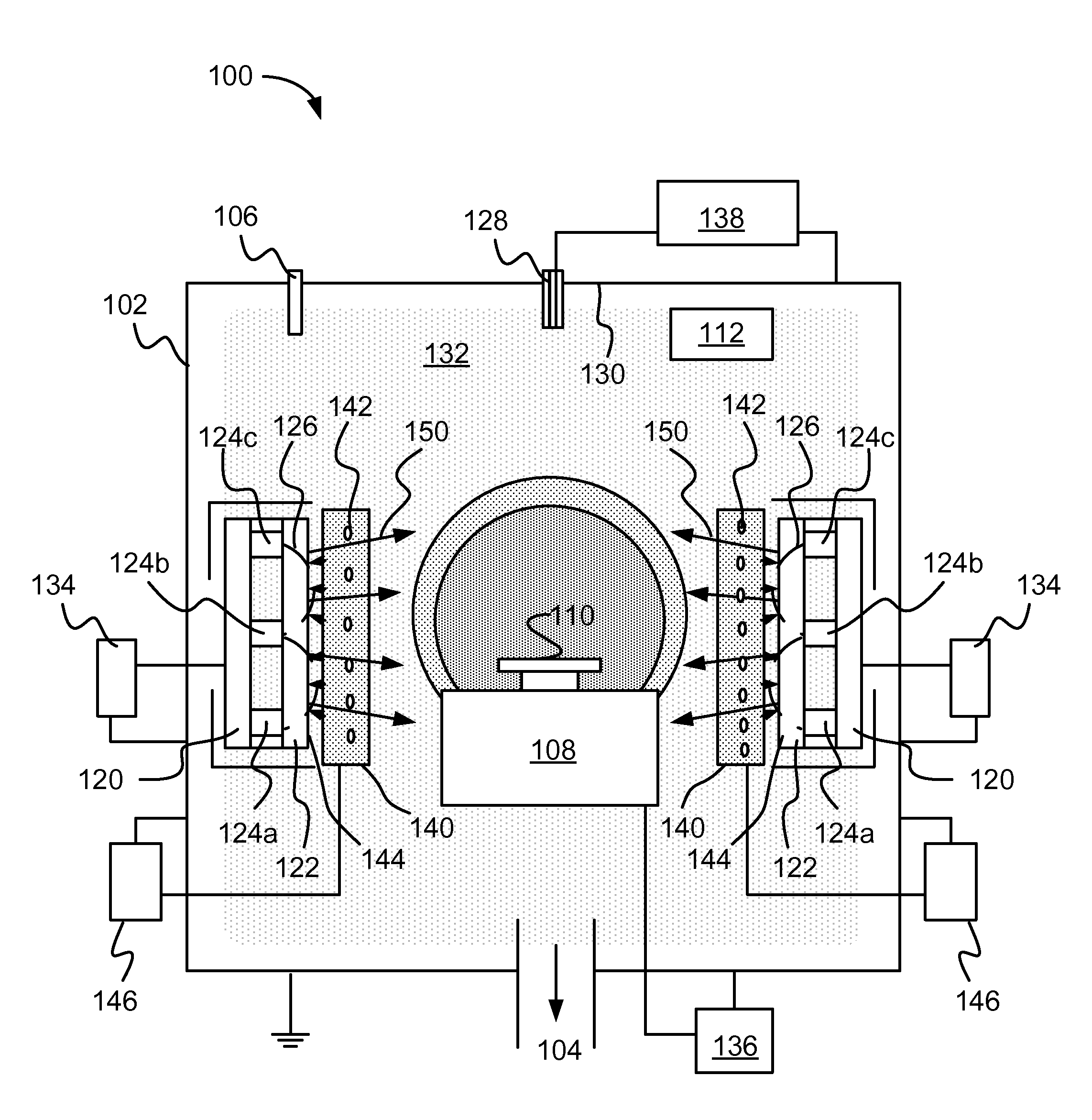
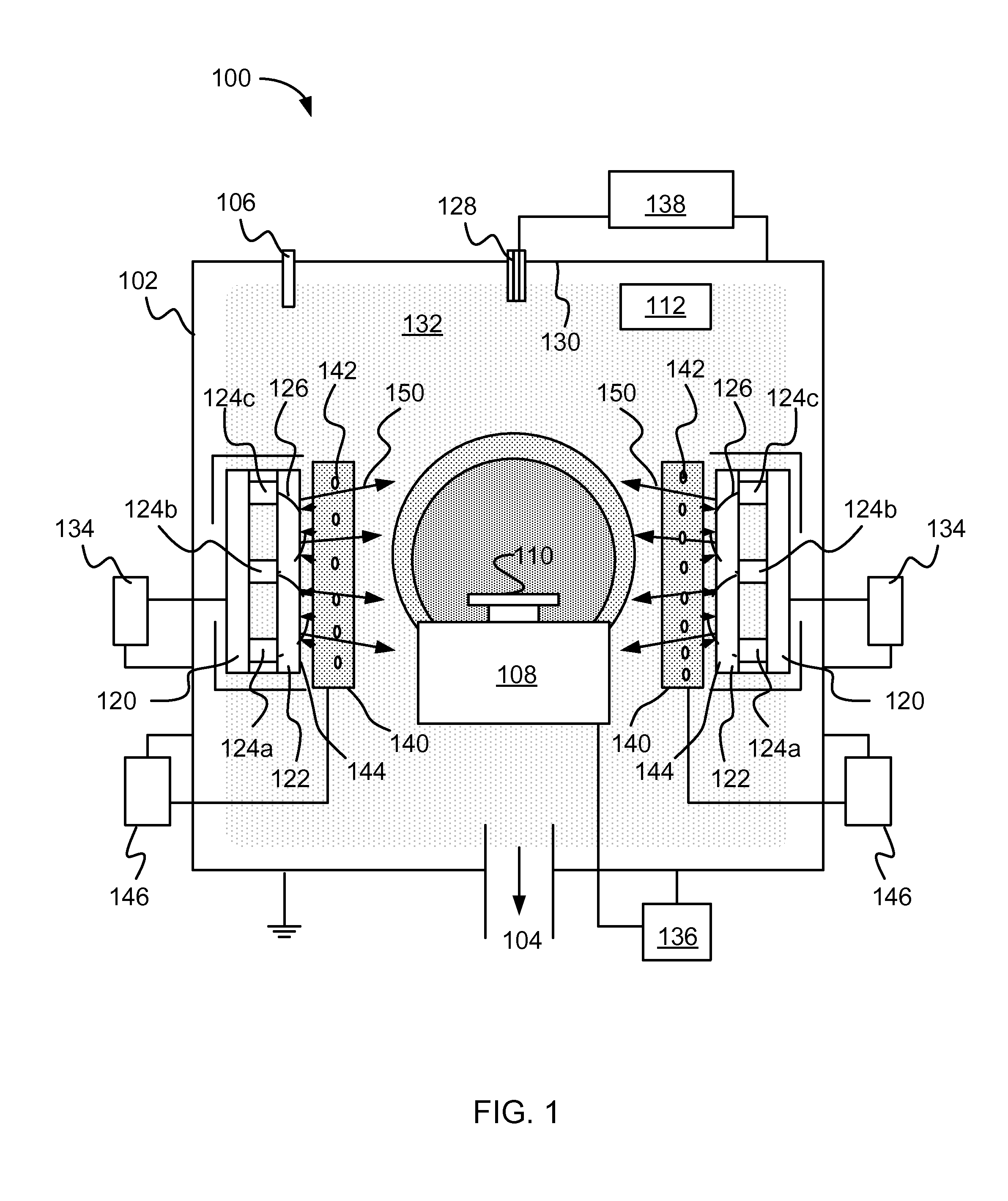
[0084]A DC magnetron with a disc titanium target 100 mm in diameter was used for magnetron sputtering titanium in an Ar—N2 plasma during deposition of TiN coatings. The coatings were deposited on disc SS coupons 3 cm diameter×0.3 cm thick. The substrates to be coated were ultrasonically cleaned in acetone and isopropyl alcohol prior to loading in a vacuum processing chamber. The substrates were positioned on a rotary substrate holder, wherein the diameter of rotation was 200 mm, bringing the substrates to a distance of 20 cm from the magnetron target, wherein the substrate holder was connected to RF 13.56 MHz bias power supply. The substrates were preheated to 250° C. as determined by thermocouple measurements using radiation heaters installed behind rotary substrate holder in the vacuum chamber.

[0085]An ionizing grid of tungsten filaments included filaments having a diameter of 250 μm was installed in front of the magnetron target at a distance of 10 mm from the target surface as i...

example 2

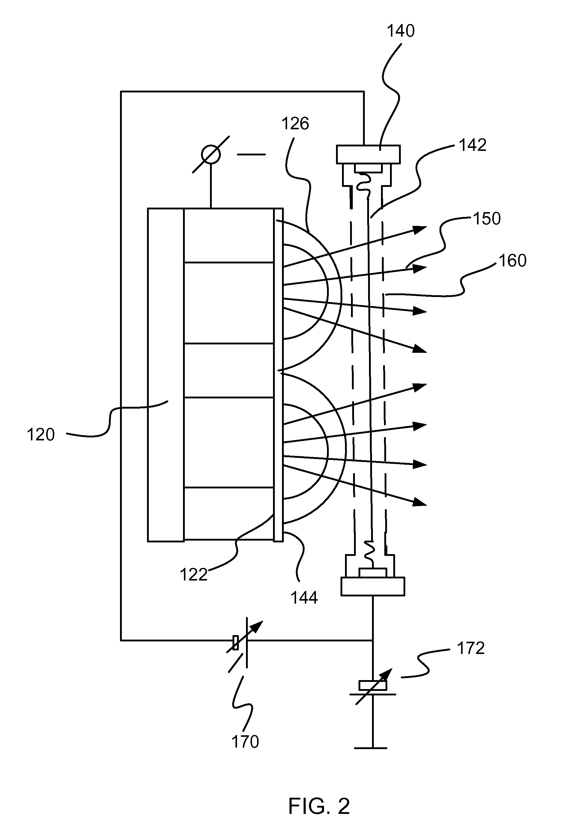
[0087]A nickel coating was deposited using the apparatus illustrated in FIG. 2. The cathode target described above in Example 1 was used. Similarly, substrate coupons were installed 20 cm from the magnetron target on the rotary substrate holder having a 500 mm diameter of rotation. The substrates were preheated to 250° C. by conventional heaters installed in the coating chamber. The ionizing filament grid included tungsten filaments having a 250 μm diameter. The filaments were connected to an RF generator with a frequency of 13.56 MHz. The autopolarization bias potential, which is a DC voltage induced on filament grid by applying the RF bias in a presence of plasma was set to 150 volts and the heating power supply was disconnected from the filament grid. The DC autopolarization bias was measured by voltameter connected to the grid via LC-filter. The remainder of the processing parameters was the same as in Example 1.

[0088]FIG. 24 illustrates the ion current collected by a 10 cm diam...

example 3

[0090]A TiN coating was deposited using the apparatus illustrated in FIG. 2. The cathode target described above in Example 1 was used. Similarly, substrate coupons were installed 20 cm from the magnetron target on the rotary substrate holder having a 500 mm diameter of rotation. The substrates were preheated to 250° C. by conventional heaters installed in the coating chamber. The ionizing filament grid included tungsten filaments having a 250 μm diameter. The filaments were connected to a DC bias power supply to set up 100 volts of bias potential to the filament grid. The heating power supply was also connected to the filament grid and the heating current was set to 12 amperes to reach the thermionic emission temperature of about 2100° C. of the tungsten filament grid. The remainder of the processing parameters was the same as in Example 1.


PUM

PropertyMeasurementUnit
Lengthaaaaaaaaaa
Carrier concentrationaaaaaaaaaa
Poweraaaaaaaaaa

Abstract

A vapor deposition coating system including a metal vapor source, a power supply coupled to the metal vapor source, at least one thermionic ionizing grid including one or more thermionic filaments, wherein the ionizing grid is at least partially located within a region having a metal atom flow density in the range of 1E14m−3 to 1E24m3 when the power supply coupled to the metal vapor source is energized; and a heating power supply coupled to the thermionic ionizing grid, wherein the heating power supply is configured to heat the filaments to the thermionic emission temperature of the filaments. The thermionic discharge is energized between the thermionic ionizing grid connected to the negative pole of power supply as a cathode and the anode connected to the positive pole of the power supply.

Description

FIELD OF THE INVENTION[0001]The present disclosure relates to a method and apparatus for producing an ionized vapor deposition coating.BACKGROUND[0002]Vapor deposition may be generally understood as a mechanism of producing a film or coating and may include physical vapor deposition and chemical vapor deposition. In physical vapor deposition, a vaporized form of the coating material may condense on a substrate surface forming the coating. In chemical vapor deposition, one or more precursors may react and / or decompose on a substrate surface forming the coating. Conventional methods of vapor deposition, such as electron beam physical vapor deposition and magnetron sputtering may be used to produce metallic coatings. However, coatings produced in such a manner may exhibit relatively low density, poor adhesion, poor structure and / or poor morphology.SUMMARY OF THE INVENTION[0003]An aspect of the present disclosure relates to a vapor deposition coating system. The system may include a met...

Claims


Application Information

Patent Timeline
IPC IPC(8): C23C14/22C23C14/02C23C14/14
CPCC23C14/0641C23C14/355C23C14/165
Inventor GOROKHOVSKY, VLADIMIR
Owner SOUTHWEST RES INST
Why Eureka
Try Eureka