
Heat integrated process for producing high quality pyrolysis oil from biomass

Inactive Publication Date: 2012-05-10
PHILLIPS 66 CO
View PDF9 Cites 18 Cited by
  • Summary
  • Abstract
  • Description
  • Claims
  • Application Information

AI Technical Summary

Benefits of technology

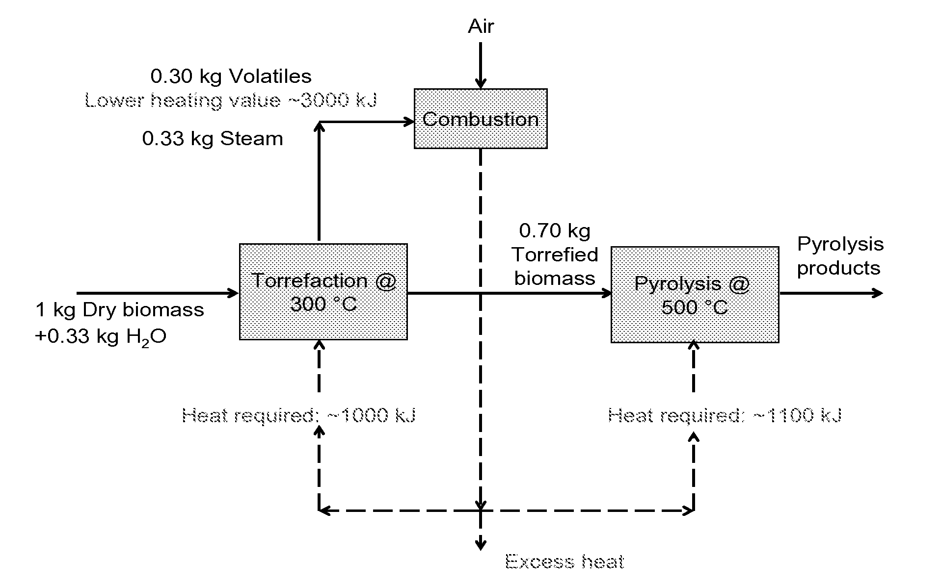
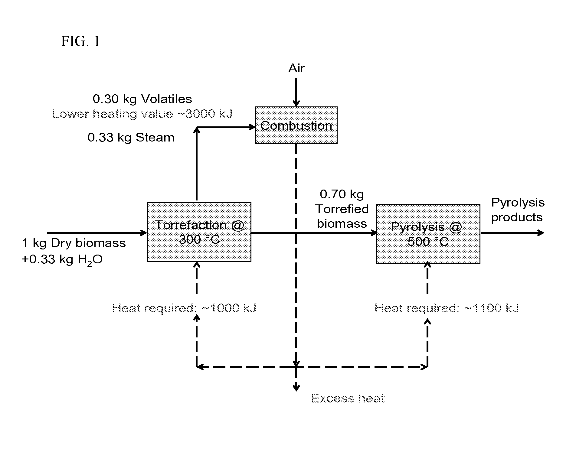
[0014]This invention discloses a heat integrated and energy saving process for producing high quality pyrolysis oil from biomass by utilizing a torrefaction pretreatment step for biomass pyrolysis processing wherein the pretreatment step improves the quality of the pyrolysis oil by reducing acidity. This invention further utilizes the gaseous product of the torrefaction step through a combustion process for heat production and recovery.

Problems solved by technology

However, pyrolysis oil obtained from a biomass fast pyrolysis process is a chemically-complex mixture of compounds including water, light volatiles, and non-volatiles.
Such oil is in general of relatively low quality and has a number of negative properties such as high acidity (which can lead to corrosion problems), substantial water content (usually in the range of 15% to 30%), variable viscosity, low heating values (about half that of diesel fuel), low cetane number, etc.
Since pyrolysis liquids typically contain between 30 to 50 wt % of oxygen, complete removal of oxygen requires a substantial consumption of hydrogen which represents a major and sometimes prohibitive cost.

Method used


Image

  • Heat integrated process for producing high quality pyrolysis oil from biomass
  • Heat integrated process for producing high quality pyrolysis oil from biomass

Examples


example 1

[0044]The comparison study of the process of torrefaction prior to pyrolysis has been performed in a micropyrolysis unit. The reactions were carried out at torrefaction temperatures ranging from 179 to 321° C. and pyrolysis temperatures ranging from 379 to 521° C. with no catalyst loading. In addition, a wide variety of biomass was tested including red oak, switchgrass, miscanthus, and corn stover pellets. Comparative pyrolysis tests were run without the torrefaction pretreatment at the same pyrolysis temperatures.

Result:

[0045]The experimental results indicating the reduction of acetic acid in the pyrolysis product due to torrefaction are shown as follows:

TABLE IAverage Acetic Acid Yield.PyrolysisTorrefaction - PyrolysisYield1,Yield1,Reduction3Biomasswt-%Concentration2, %wt-%Concentration2, %Yield, %Concentration, %Oak8.765.386.294.4028.218.1Switchgrass4.644.793.073.9634.017.3Miscanthus3.756.252.354.4137.229.4Corn1.895.410.743.2960.739.3StoverPellets1Mass of acetic acid over mass of...

example 2

[0047]As illustrated in FIG. 1, the theoretical heat available from the combustion process according to the current invention is calculated based on the assumption that 1 kg of dry biomass with 25 wt % of moisture content is torrefied at 300° C., the volatile product yield is 30% (dry biomass basis), the volatiles include CO, CO2, H2O (produced from torrefaction reaction), H2, methane, ethane, acetic acid, formic acid, and other organic materials. The calculated lower heating value (LHV) of the 0.3 kg volatiles / gases is approximately 3000 KJ. The heat produced from combustion of these volatiles is then utilized by torrefaction and / or pyrolysis steps, which require 1000 KJ, and / or 1100 KJ, respectively.

Discussion:

[0048]As discussed above, the pyrolysis oil obtained from biomass fast pyrolysis process is of relatively low quality. In general, pyrolysis oil has TAN value of approximately 100. The desired TAN value for transportation fuel is less than 10.

[0049]The results above show tha...


PUM


Abstract

This invention discloses a heat integrated and energy saving process for producing high quality pyrolysis oil from biomass by utilizing a torrefaction pretreatment step for biomass pyrolysis processing wherein the pretreatment step improves the quality of the pyrolysis oil by reducing acidity. This invention further utilizes the gaseous product of the torrefaction step through a combustion process for heat production and recovery.

Description

CROSS-REFERENCE TO RELATED APPLICATIONS[0001]This application is a non-provisional application which claims benefit under 35 USC §119(e) to U.S. Provisional Application Ser. No. 61 / 411,531, filed Nov. 9, 2010, entitled “HEAT INTEGRATED PROCESS FOR PRODUCING HIGH QUALITY PYROLYSIS OIL FROM BIOMASS,” which is incorporated herein in its entirety.STATEMENT REGARDING FEDERALLY SPONSORED RESEARCH OR DEVELOPMENT[0002]None.FIELD OF THE INVENTION[0003]The present invention relates generally to the conversion of biomass to fuel range hydrocarbons.BACKGROUND OF THE INVENTION[0004]Due to governmental legislation as mandated in the Renewable Fuels Standards (RFS), the use of renewable energy sources is becoming increasingly necessary to reduce emissions of carbon based fuels and provide alternatives to petroleum based energy and feedstock. One of the alternatives being explored is the use of biomass. Biomass is any carbon containing material derived from living or formerly living organisms, such...

Claims


Application Information

Patent Timeline
IPC IPC(8): C07C1/00
CPCC10B49/10C10B49/22C10B53/02Y02E50/15C10C5/00C10L9/083Y02E50/14C10B57/02Y02E50/10Y02P20/145
Inventor GONG, KENINGDAUGAARD, DAREN EINARPLATON, ALEXANDRUCANTU, TERRY S.WARDINSKY, MICHAEL D.
Owner PHILLIPS 66 CO
Learn More