Anisotropic conductive adhesive for ultrasonic wave adhesion, and electronic parts connection method using same
- Summary
- Abstract
- Description
- Claims
- Application Information
AI Technical Summary
Benefits of technology
Problems solved by technology
Method used
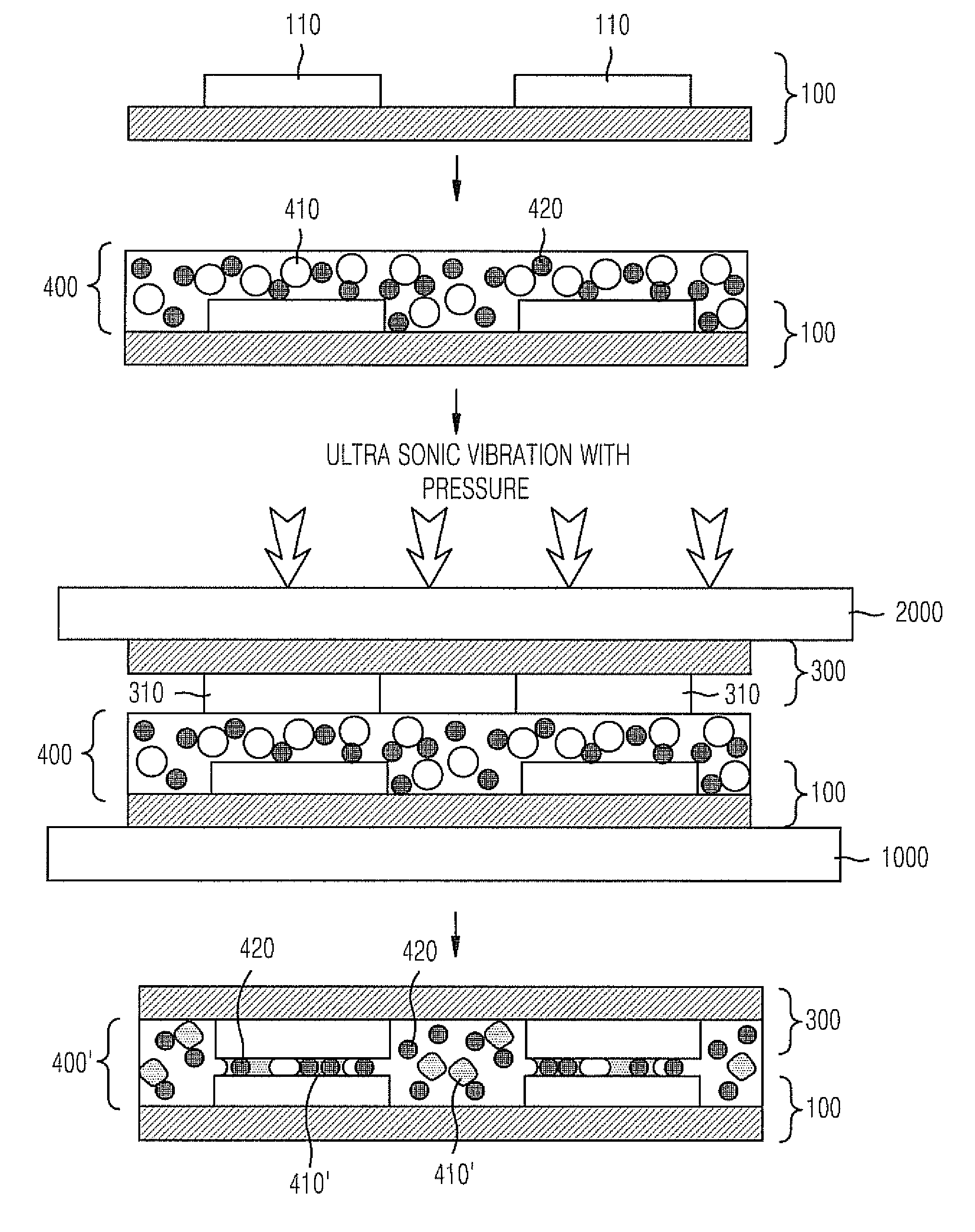
Image

Examples
Embodiment Construction
[0044]Hereinafter, exemplary embodiments of an anisotropic conductive adhesive and a method of interconnecting electronic components according to the present invention will be described in detail with reference to the accompanying drawings. The present invention may, however, be embodied in different forms, and should not be constructed as being limited to the embodiments set forth herein. Rather, these embodiments are provided so that this disclosure will be thorough and complete, and will fully convey the scope of the present invention to those skilled in the art.
[0045]Throughout the disclosure, like reference numerals refer to like parts throughout the various figures and embodiments of the present invention.
[0046]In this case, in the technical and scientific terms described herein, if a different definition is not described, it means that a person having ordinary skill in the art to which this invention pertains can typically understand the invention. In addition, in the descrip...
PUM
| Property | Measurement | Unit |
|---|---|---|
| Percent by mass | aaaaa | aaaaa |
| Percent by mass | aaaaa | aaaaa |
| Particle diameter | aaaaa | aaaaa |
Abstract
Description
Claims
Application Information
PatSnap Eureka turns technology decisions into work you can execute. Powered by our Innovation Knowledge Graph, it runs expert workflows across engineering, life sciences, materials and intellectual property. Get your review-ready output in minutes.


