Implementation of CO-Gases for Germanium and Boron Ion Implants

a technology of germanium and boron ion implants and co-gases, which is applied in the field of ion implantation and fabrication of semiconductor devices, can solve the problems of low vapor pressure, condense on the interior surfaces of sources, and failure of ion sources, so as to facilitate ion implantation processes and improve the performance of ion sources. , the effect of reducing damage to the ion source chamber

Active Publication Date: 2012-05-17
AXCELIS TECHNOLOGIES
View PDF8 Cites 39 Cited by
  • Summary
  • Abstract
  • Description
  • Claims
  • Application Information

AI Technical Summary

Benefits of technology

[0011]Aspects of the invention facilitate ion implantation processes by providing a method for improving performance of an ion source in an ion implanter in which at least one co-gas is introduced into an ion source chamber together with a fluorine-containing dopant sou...

Problems solved by technology

When the ion source is operated with a molecular source gas, species in addition to the desired species for implantation are often produced, resulting in ion source failure due to the accumulation or corrosive properties of these species generated during disassociation/ionization of the source gases.
Some of these species may have very low vapor pressures, and as a result condense on the interior surfaces of the source.
These solid deposits may interfere with ion source operation over time, for example by changing the electrical characteristics of the walls or partially blocking t...

Method used


Image

  • Implementation of CO-Gases for Germanium and Boron Ion Implants
  • Implementation of CO-Gases for Germanium and Boron Ion Implants
  • Implementation of CO-Gases for Germanium and Boron Ion Implants

Examples


Embodiment Construction

[0021]The invention will now be described with reference to the attached drawings, wherein like reference numerals are used to refer to like elements throughout. It will be appreciated by those skilled in the art that the invention is not limited to the exemplary implementations and aspects illustrated and described hereinafter.

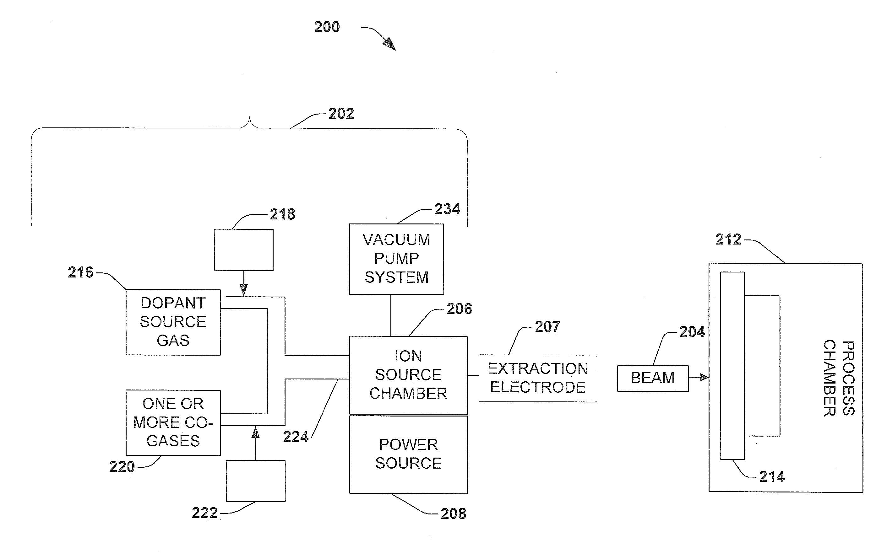
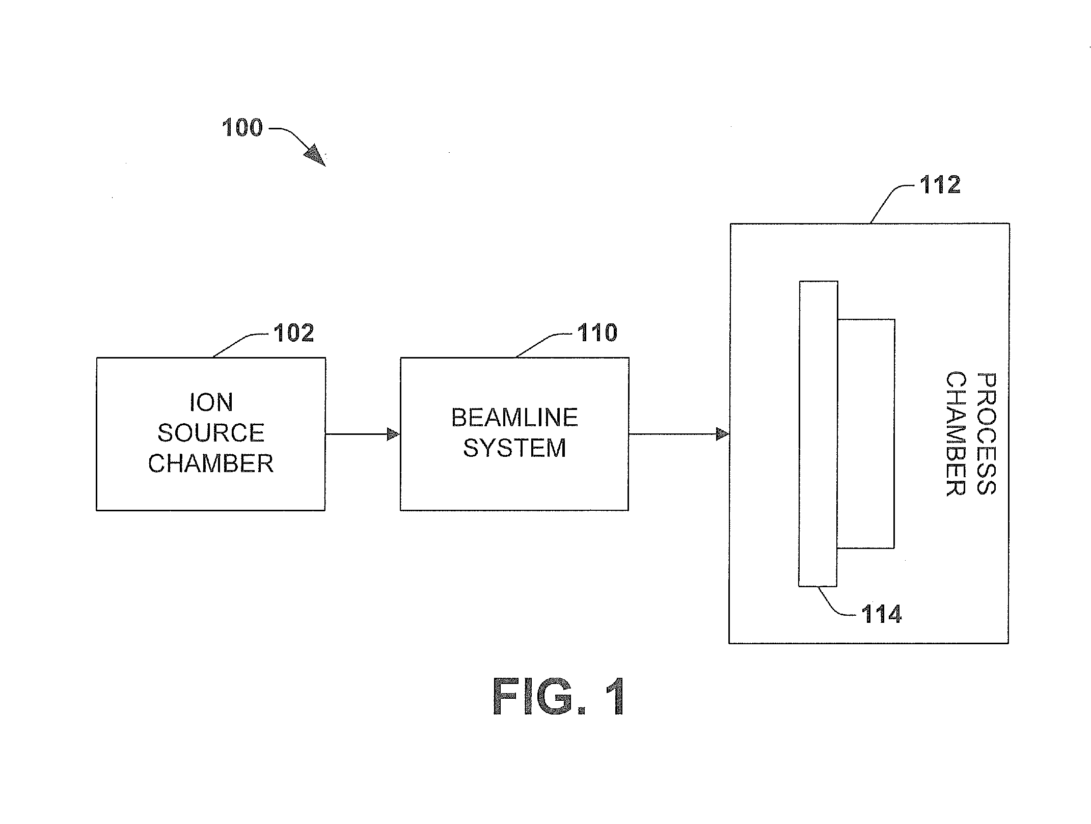
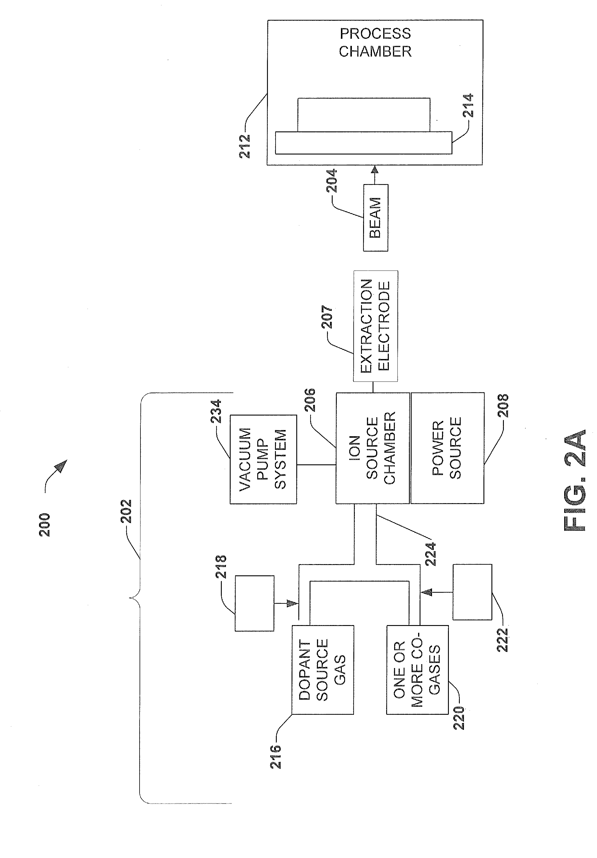
[0022]Referring initially to FIG. 2, an ion implantation system 200 suitable for implementing one or more aspects of the invention is depicted in block diagram form.

[0023]The system 200 includes an ion source assembly 202 for producing an ion beam 204 along a beam path. The ion source assembly 202 includes, for example, a plasma source 206 with an associated power source 208. The plasma source 206 may, for example, comprise a relatively long plasma confinement chamber from which an ion beam is extracted and accelerated.

[0024]A supply of a fluorine-containing dopant gas source 216 is coupled to the ion source chamber 206 via an inlet 224. Dopant gas controller...


PUM


Abstract

An ion implantation system for improving performance and extending lifetime of an ion source is disclosed. A fluorine-containing dopant gas source is introduced into the ion chamber along with one or more co-gases. The one or more co-gases can include hydrogen or krypton. The co-gases mitigate the effects caused by free fluorine ions in the ion source chamber which lead to ion source failure.

Description

FIELD OF INVENTION[0001]The present invention relates generally to semiconductor device fabrication and ion implantation, and more particularly to a method of improving performance and extending the lifetime of an ion source in an ion implanter.BACKGROUND OF THE INVENTION[0002]Ion implantation is a physical process that is employed in semiconductor device fabrication to selectively implant dopant into semiconductor and / or wafer material. Thus, the act of implanting does not rely on a chemical interaction between a dopant and semiconductor material. For ion implantation, dopant atoms / molecules are ionized, accelerated, formed into a beam, analyzed, and swept across a wafer, or the wafer is swept through the beam. The dopant ions physically bombard the wafer, enter the surface and come to rest below the surface, at a depth related to their energy.[0003]Referring to FIG. 1 ion implanters or ion implantation systems typically include three sections or subsystems: (i) an ion source chamb...

Claims


Application Information

Patent Timeline
IPC IPC(8): G21G5/00
CPCH01J37/08H01J2237/022H01J2237/006H01J37/3171
Inventor COLVIN, NEIL K.HSIEH, TSEH-JEN
Owner AXCELIS TECHNOLOGIES
Why Eureka
Try Eureka