Inverter control device and inverter control method

a technology of inverter control and control method, which is applied in the direction of electric variable regulation, process and machine control, instruments, etc., can solve the problems of transformer current not flowing, transformer current becoming unstable, regeneration diodes of switching elements to generate more heat, etc., to suppress the heat generation of switching elements, control well and accurately, and suppress the effect of switching element heat generation

Active Publication Date: 2012-05-17
PANASONIC CORP
View PDF2 Cites 22 Cited by
  • Summary
  • Abstract
  • Description
  • Claims
  • Application Information

AI Technical Summary

Benefits of technology

[0065]The present invention, in order to solve the above-described problems, provides an inverter control device that prevents a regenerative current to suppress heat generation for whatever the magnitude of a signal such as an error amplification signal of the inverter control device and controls an output current well accurately.
[0067]This configuration allows the inverter control device to exercise control by PWM control method and phase control method. Hence, when an error amplification signal is larger than a predetermined threshold, PWM control method is used to prevent a regenerative current to suppress heat generation of a switching element. When smaller, phase control method is used to enable an output current to be controlled well accurately.
[0069]This configuration allows the inverter control device to exercise control by PWM control method and phase control method. Hence, when an error amplification signal is larger than a predetermined threshold, PWM control method is used to prevent a regenerative current to suppress heat generation of a switching element. When smaller, phase control method is used to enable an output current to be controlled well accurately.
[0071]This configuration allows the inverter control device to exercise control by PWM control method and phase control method. Hence, when an error amplification signal is larger than a predetermined threshold, PWM control method is used to prevent a regenerative current to suppress heat generation of a switching element. When smaller, phase control method is used to enable an output current to be controlled well accurately.
[0074]As described thereinbefore, the present invention allows using two control methods: PWM control method and phase control method. Hence, when an error amplification signal is larger than a predetermined threshold, PWM control method is used to prevent a regenerative current to suppress heat generation of a switching element. When smaller, phase control method is used to enable an output current to be controlled well accurately.

Problems solved by technology

That is, a switching element does not conduct due to such as delay operation of the driving circuit during minimum power output; a transformer current does not flow; and a transformer current becomes unstable near the minimum conduction width.
Accordingly, conduction (i.e. a flow of a transformer current) becomes unstable when the conduction time approaches the minimum conduction width, which sometimes causes a transformer current not to flow.
However, the large area size of the waveform indicated by the horizontal stripes in the waveform of a transformer current brings about a large regenerative current, thereby causing the regeneration diode of the switching element to generate more heat.
Since this regenerative current is interrupted, a regeneration turn-off power loss is generated.
Consequently, the switching element cannot be driven, or highly accurate control cannot be exercised in practice.
Such a situation is of a problem particularly when requiring stable control on an output current in a range of several amperes, as in a TIG welding machine.
This phenomenon undesirably causes heat generation of an element and transformer saturation due to an unstable transformer current near a minimum drive width because the switching element is inadequately driven due to insufficient power for driving the gate of the switching element.
Accordingly, a large capacitance of the snubber capacitor leads to difficulty in control at low output, which prevents an output current or output voltage of the welding machine from falling to a minimum output.
This brings about a large regenerative current, thereby causing more heat generation in a regeneration diode contained in a switching element and a higher switching loss at the transistor.
As described above, phase control method involves a large regenerative current and difficulty in preventing heat generation in the device.
Meanwhile, PWM control method has difficulty in controlling a minute current well accurately.

Method used


Image

  • Inverter control device and inverter control method
  • Inverter control device and inverter control method
  • Inverter control device and inverter control method

Examples


first exemplary embodiment

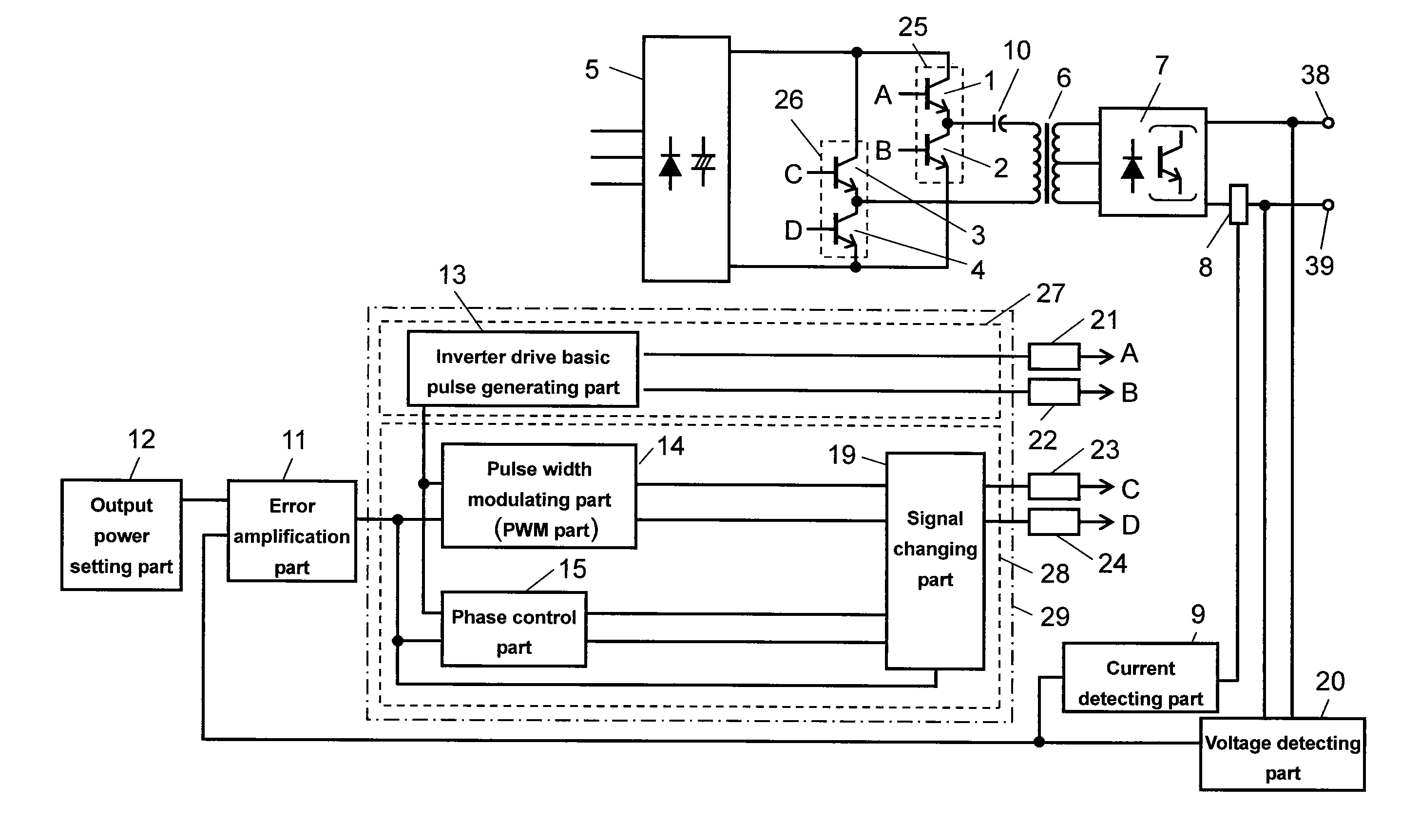
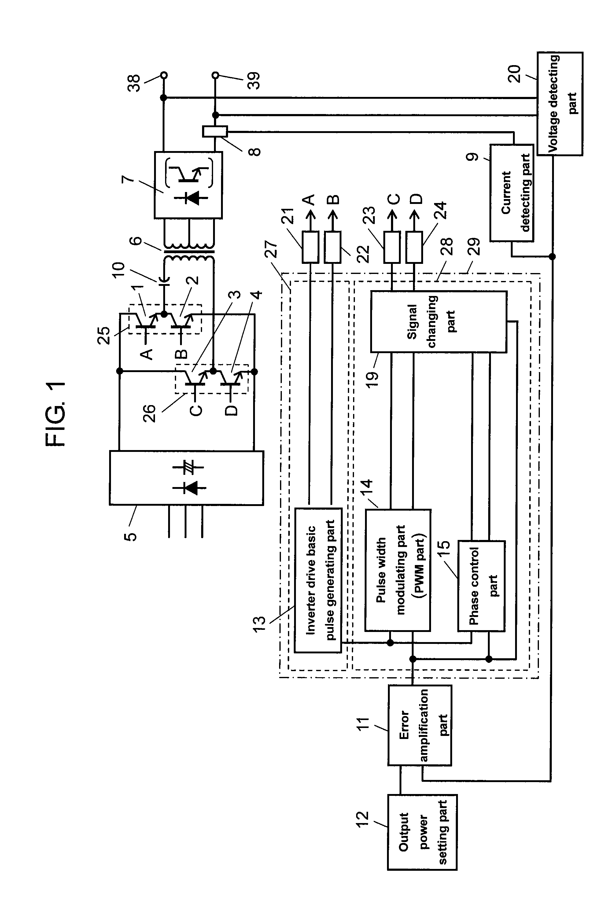
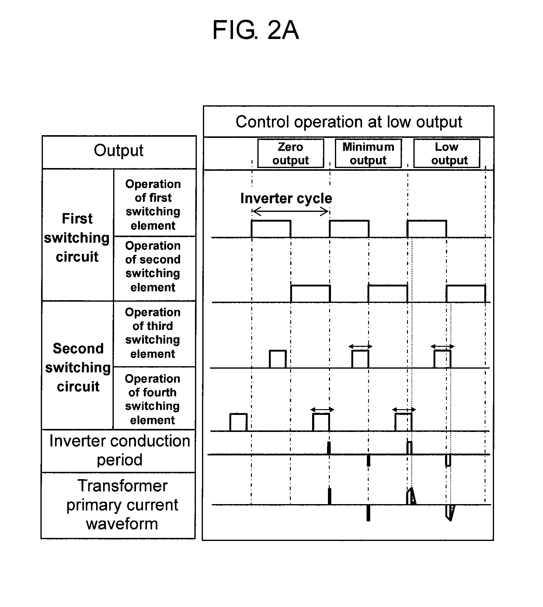
[0108]A description is made of an arc welding machine using an inverter control device according to the first exemplary embodiment using FIG. 1 and FIGS. 2A through 2C. FIG. 1 shows an outline structure of substantial parts of the arc welding machine. FIGS. 2A through 2C are schematic diagrams showing operation of the components of the arc welding machine. FIGS. 2A through 2C illustrate operation of the arc welding machine, specifically operation of a switching element, an inverter conduction period, and a waveform of a transformer primary current at low output (FIG. 2A), middle output (FIG. 2B), and high output (FIG. 2C) for welding.

[0109]Here, low, middle, and high output for welding are classified on the basis of the magnitude of an error amplification signal from error amplification part 11 (described later), for example. Specifically, if the magnitude is lower than a predetermined first threshold, the output is low; if between the predetermined first threshold and a predetermin...

second exemplary embodiment

[0142]A description is made of an arc welding machine including an inverter control device of the second exemplary embodiment using FIG. 3 and FIGS. 4A through 4C. FIG. 3 shows an outline structure of substantial parts of the inverter control device. FIGS. 4A through 4C illustrate operation of the inverter control device, specifically operation of a switching element, an inverter conduction period, and a waveform of a transformer primary current at low output (FIG. 4A), middle output (FIG. 4B), and high output (FIG. 4C) for welding.

[0143]In this embodiment, a component or portion same as that in the first embodiment is given the same reference mark to omit its detailed description.

[0144]The principal point different from the first embodiment is the configuration of inverter control part 29. Specifically, the second embodiment includes driving pulse width changing part 17 as described later. Further, signal changing part 19 outputs an output signal selectively from pulse-width modula...

third exemplary embodiment

[0176]A description is made of the inverter control device of an arc welding machine according to the third exemplary embodiment using FIGS. 5 through 7. FIG. 5 shows an outline structure of substantial parts of the inverter control device. FIGS. 6A through 6C schematically illustrate operation of the inverter control device, specifically operation of a switching element, an inverter conduction period, and a waveform of a transformer primary current at low output (FIG. 6A), middle output (FIG. 6B), and high output (FIG. 6C) for welding. FIGS. 7A and 7B illustrate inverter operation, showing changes in operating state. FIG. 7A shows the entire waveform for one cycle. FIG. 7B shows conduction states of the switching elements and operating states of a circuit current in the time areas indicated by T1 through T5 in FIG. 7A.

[0177]In FIG. 7A, part L1 surrounded by the solid-line oval indicates that switching loss is generated; and L2 surrounded by the broken-line oval, not generated.

[0178...


PUM

PropertyMeasurementUnit
frequencyaaaaaaaaaa
charging currentaaaaaaaaaa
output currentaaaaaaaaaa

Abstract

An inverter control device drives one of the two switching circuits with a fixed conduction width and changes the control method of the other switching circuit between pulse-width modulation, phase control method, and drive signal width control method by phase control method according to an output state, to implement highly accurate control at low output while suppressing heat generation of a switching element.

Description

TECHNICAL FIELD[0001]The present invention relates to an inverter control device, particularly to a device for controlling an inverter circuit for controlling welding output power used in a welding machine that processes a processed object by arc discharge, and to a method of controlling the circuit.BACKGROUND ART[0002]A device (e.g. welding machine) that discharges arc between an electrode and a processed object (referred to as parent material, hereinafter) to melt the parent material for processing typically includes a power control circuit for controlling an output current flowing between the electrode and the parent material or output voltage applied between them.[0003]In recent years, such a power control circuit has been usually formed of an inverter circuit including a high-speed switching element and a power conversion transformer, becoming widely used as an inverter-controlled welding machine.[0004]Such an inverter-controlled welding machine typically includes a full-bridge...

Claims


Application Information

Patent Timeline
Patent Type & Authority Applications(United States)
IPC IPC(8): H02M3/335
CPCB23K9/067B23K9/073B23K9/09B23K9/1043Y02B70/1491B23K9/173H02M7/53871H02M2001/0048B23K9/167H02M1/0048Y02B70/10Y02P70/10
Inventor OHSAKI, NORIKAZUTANAKA, YOSHIAKITABATA, YOSHIYUKI
Owner PANASONIC CORP
Why Eureka
Try Eureka