Nerve Mapping Surgical System and Method of Use of Dual Function Surgical Instrument Within Such System

Inactive Publication Date: 2012-05-17
PROPEP
View PDF5 Cites 6 Cited by
  • Summary
  • Abstract
  • Description
  • Claims
  • Application Information

AI Technical Summary

Benefits of technology

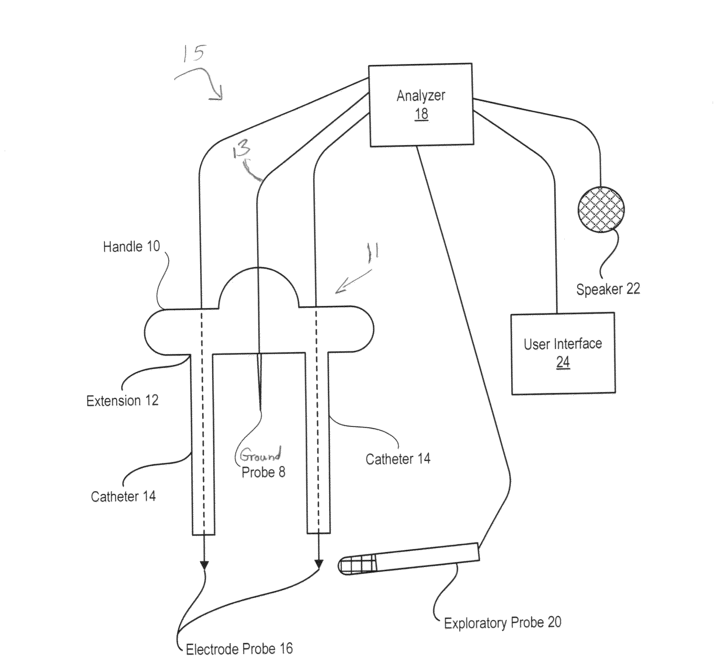
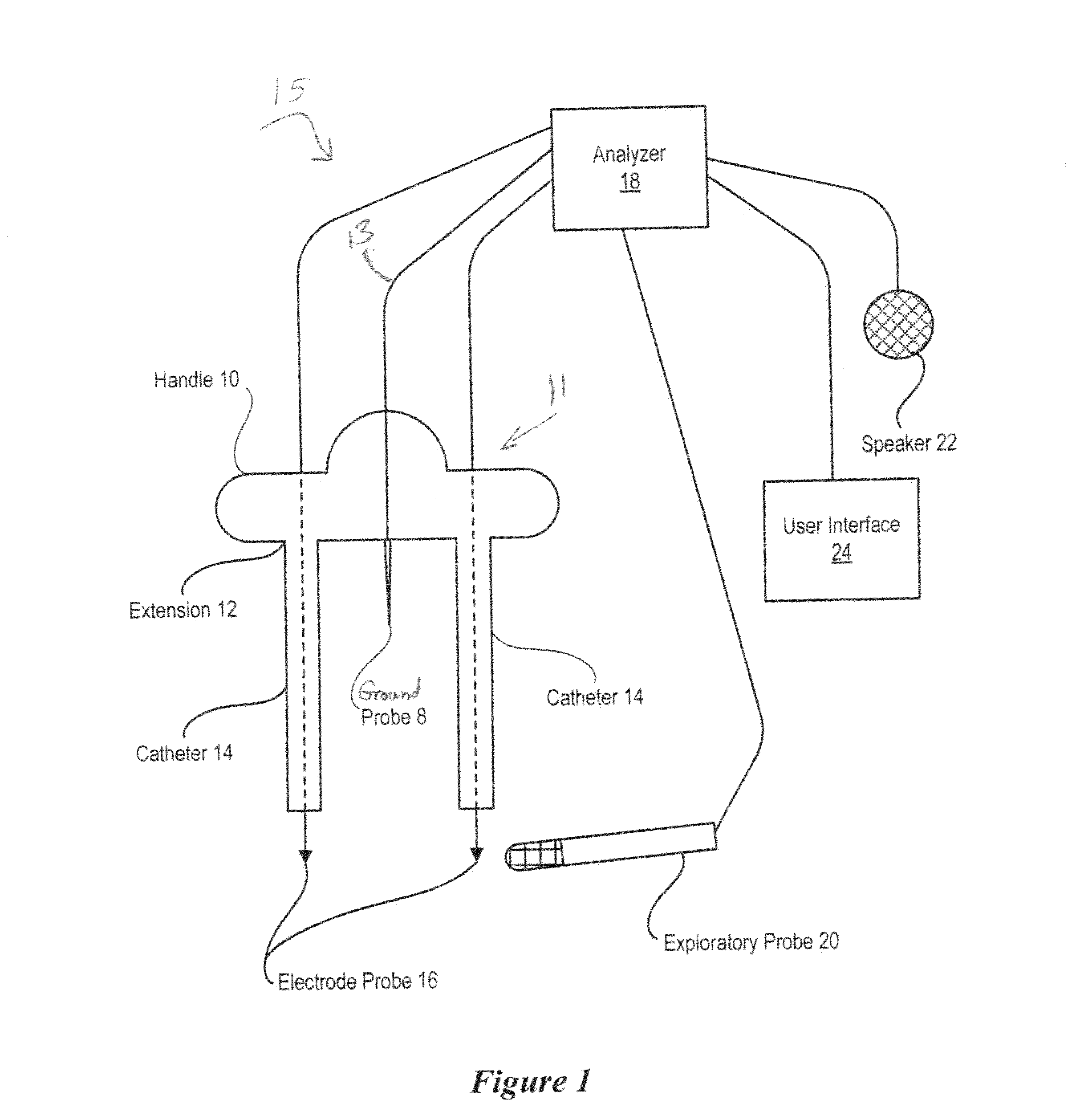
[0008]Therefore a need has arisen for a rapid, efficient and precise system and method which aids in the detection and mapping of nerves during laparoscopic surgery. In accordance with the present invention, systems and methods are provided which substanti

Problems solved by technology

Such open surgery entails a number of known risks including infection, inadvertent damage to other organs and structures, scarring, and loss of blood.
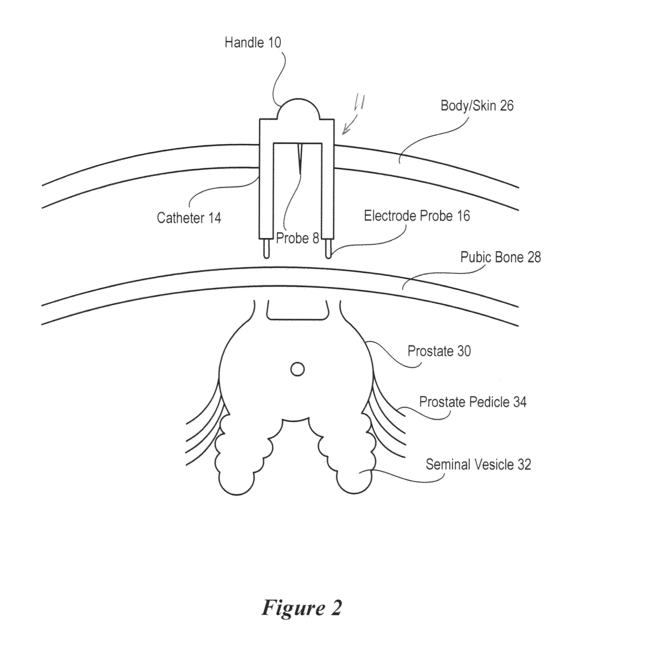
Because the area around the prostate is rich in nerves and muscles that support sexual and urinary functions, a radical prostatectomy can cause severe side effects, including sexual dysfunction and incontinence.
For example, up to half of conventionally-performed radical prostatectomies result in permanent erectile dysfunction.
Although laparoscopic and robotic surgery has shown promising potential in reducing erectile dysfunction as a side effect of prostate gland removal, erectile dysfunction

Method used


Image

  • Nerve Mapping Surgical System and Method of Use of Dual Function Surgical Instrument Within Such System
  • Nerve Mapping Surgical System and Method of Use of Dual Function Surgical Instrument Within Such System
  • Nerve Mapping Surgical System and Method of Use of Dual Function Surgical Instrument Within Such System

Examples


second embodiment

[0039]While having some similarities in function, electrode probe delivery device 110 is structured quite differently than the electrode probe delivery device 11 of FIG. 1. In this second embodiment the electrode “introducer” or electrode probe delivery device 110 includes an elongated insertion guide 121 having base plate 123 mounted transversely at one end thereof. An aperture 124, indicated in FIG. 10, is defined by base plate 123 and permits passage through the base plate of catheter 140. The shape of aperture 124 may be annular, groove-like or otherwise shaped, as may be convenient for manufacture and / or use. Base plate 123 is preferably (although not necessarily) provided with a slightly concave curved surface 123A which is positioned downwardly, proximate the patient and usually against the patient's abdominal wall during use, as in the position shown in FIG. 6. Base plate 123 is further preferably provided on its lower, or concave, surface 123A with a coating of a suitable s...

first embodiment

[0044]The nerves of interest (e.g. erectile nerves) are stimulated more or less depending upon the proximity of the dual function probe when functioning as an exploratory probe 200. Initial searching for the nerve is performed at relatively high stimulus intensities, such as up to 3.5 milliamp, or even possibly as high as 10 milliamp of current. Searching is performed by placing exploratory probe 200 at several places proximate the presumed pathway of the nerve and listening of an auditory response from a speaker (not shown, but similar to speaker 22 in the first embodiment), as well as a visual confirmation on user interface 240, as provided by analyzer 180 that reflects the strength of the electrical potential received at electrode probe 160. Once the nerve's general pathway is mapped, the stimulus intensity provided at exploratory probe 200 can be reduced, such as to a level of one-half a milliamp, to map the nerve's location more precisely.

[0045]Referring to FIG. 11, in this alt...


PUM


Abstract

A surgical system has an electrode probe, an analyzer, a bipolar instrument, a bipolar power supply and a switch, the switch in communication with the analyzer, the bipolar power supply and the bipolar instrument, to permit alternate use of the bipolar instrument as a surgical instrument and use as an exploratory probe. An electrode probe delivery device has a base plate, an insertion guide connected to and extending from the base plate and formed for receipt of an electrode probe. A catheter on the device permits receipt of at least one electrode probe and a handle connects to the catheter and permits movement thereof such that the catheter is passable through the base plate for introduction into a patient.

Description

CROSS REFERENCE TO RELATED APPLICATION[0001]The present application is a continuation-in-part of and relies upon and claims the benefit of the filing date of pending application Ser. No. 11 / 745,505. System and Method for Laparoscopic Nerve Detection, filed May 8, 2007.BACKGROUND OF THE INVENTION[0002]1. Field of the Invention[0003]The present invention relates in general to the field of laparoscopic surgery, and more particularly, to a surgical system and method of use of a dual function surgical probe within the system to facilitate detection and mapping of nerve locations.[0004]2. Description of the Related Art[0005]Traditionally, surgery on internal body parts was performed by cutting an incision in the skin to access the internal body parts. Such open surgery entails a number of known risks including infection, inadvertent damage to other organs and structures, scarring, and loss of blood. In an effort to reduce some of these risks and improve patient outcomes surgeons have deve...

Claims


Application Information

Patent Timeline
IPC IPC(8): A61B5/05A61B18/18A61B19/00
CPCA61B5/04001A61B5/4893A61B5/6848A61B2560/066A61B19/201A61B2018/1425A61B5/6877A61B5/4041A61M25/01A61B90/11A61B5/24
Inventor FAGIN, RANDYSCHIFF, JONBONFILS-RASMUSSEN, JANN
Owner PROPEP
Why Eureka
Try Eureka