Battery system containing phase change material-containing capsules in interior configuration thereof

Active Publication Date: 2012-05-31
LG ENERGY SOLUTION LTD
View PDF1 Cites 19 Cited by
  • Summary
  • Abstract
  • Description
  • Claims
  • Application Information

AI Technical Summary

Benefits of technology

[0010]Therefore, the present invention has been made in view of the above problems, and it is an object of the present invention to provide a technique for simultaneously improving service life and safety of the batte

Problems solved by technology

Rapid growth of the portable electronics industry has led to increased demand for batteries, while a rise of internal temperature of the batteries raises a great deal of problems.
For example, generation of heat upon charge/discharge of the battery under normal operating conditions leads to operation of the battery at a temperature higher than the outside thereof Consequently, occurrence of such a high temperature during operation of the battery results in rapid degradation of the battery.
Further, rapid elevation in internal temperature of the battery under abnormal operating conditions is a leading cause of battery explosion.
Even though heat generation within a certain limit may be of help to operation of the battery, temperatures outside a spe

Method used


Image

  • Battery system containing phase change material-containing capsules in interior configuration thereof
  • Battery system containing phase change material-containing capsules in interior configuration thereof
  • Battery system containing phase change material-containing capsules in interior configuration thereof

Examples


Example

Example 1

1-1. Preparation of Cathode

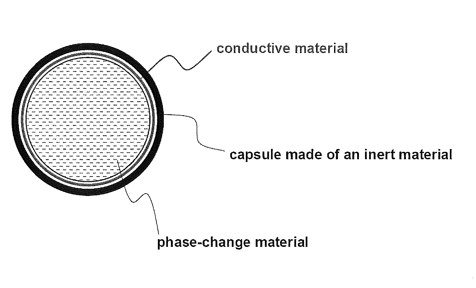
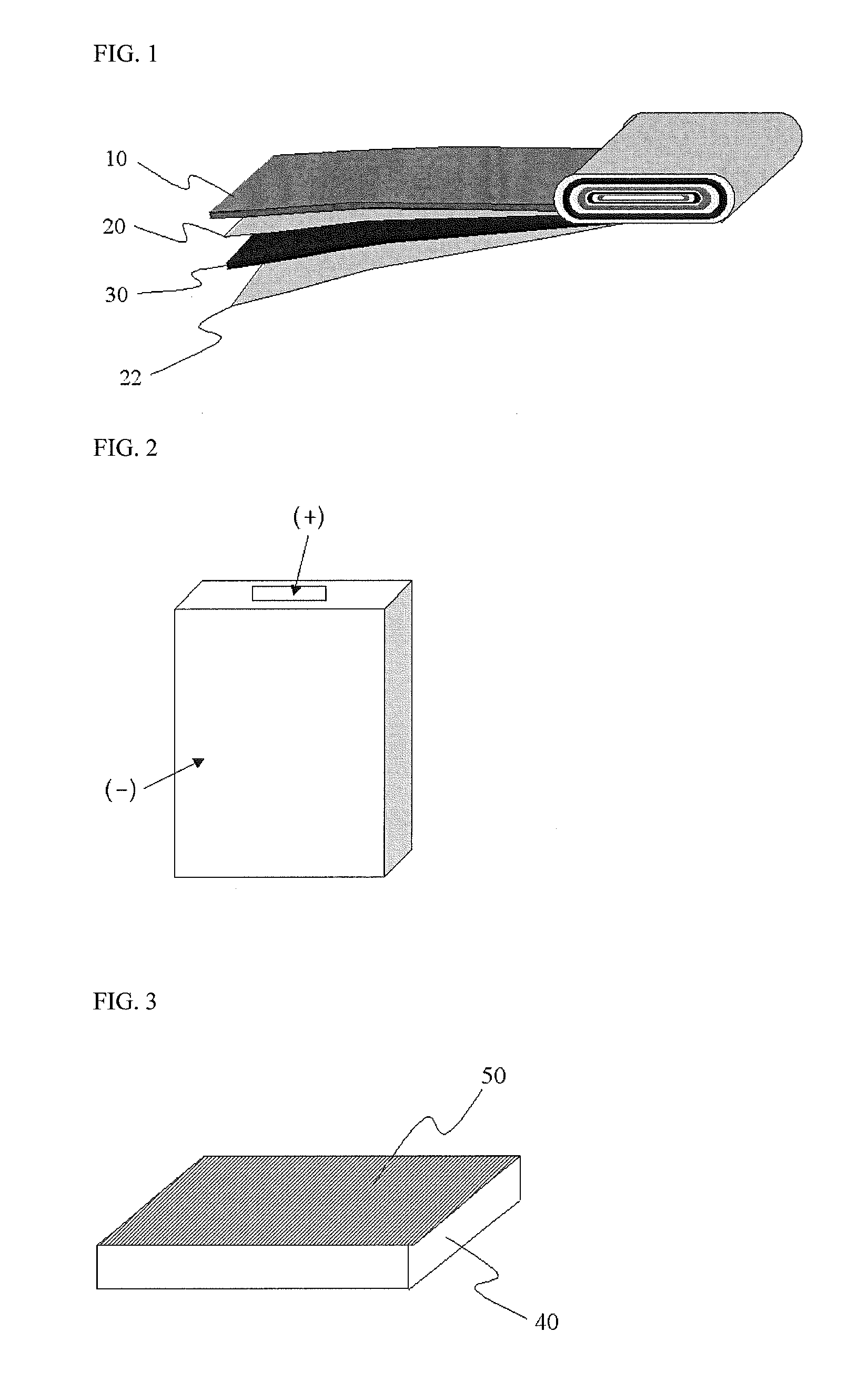
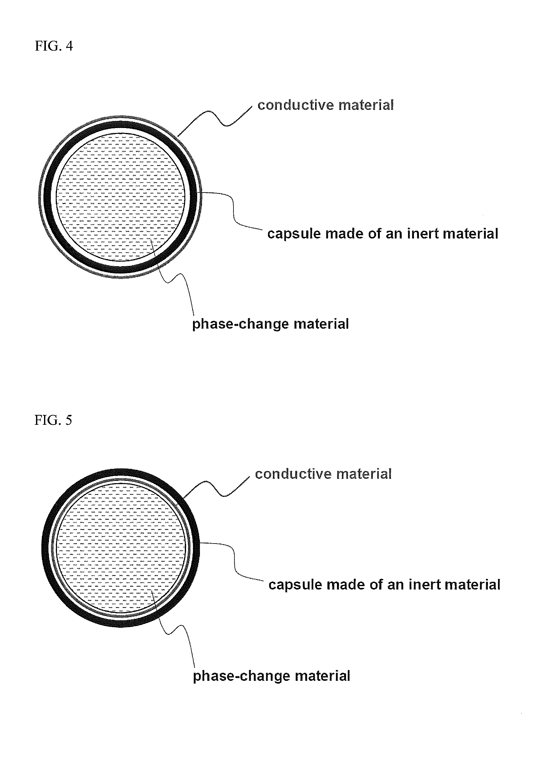
[0043]93% by weight of LiCoO2 as a cathode active material, 2% by weight of phase-change particles, 2.5% by weight of Super-P (a conductive agent) and 2.5% by weight of PVDF (a binder) were added to NMP (N-methyl-2-pyrrolidone) as a solvent, thereby preparing a cathode mixture slurry, and the resulting slurry was coated on an aluminum current collector to prepare a cathode. The phase-change particles (available from ENET Co., Ltd., Korea) contain encapsulated, saturated paraffinic hydrocarbon having a melting point of 58° C., as a phase change material. Latent heat of the phase-change particles was 145 J / g, based on the dry weight of the microcapsule.

1-2. Preparation of Anode

[0044]95.3% by weight of artificial graphite as an anode active material, 0.7% by weight of Super-P (a conductive agent) and 4% by weight of PVDF (a binder) were added to an NMP solvent, thereby preparing an anode mixture slurry, and the resulting slurry was coated on a copper...

Example

Example 2

[0047]A battery was prepared using the same procedure as in Example 1, except that surfaces of phase-change particles were coated with carbon, and the content of carbon-coated phase-change particles used was 2.1% by weight and the content of Super-P (a conductive agent) was 2.4% by weight. Since the phase-change particles practically used were coated with 5% by weight of carbon, the content of phase-change particles alone was 2% by weight and the total content of conductive agent was 2.5% by weight when a slurry was prepared having the above-mentioned composition. Therefore, conditions for preparing the battery in this example are substantially identical to those of Example 1.

Example

Example 3

[0048]A battery was prepared using the same procedure as in Example 1, except that phase-change particles were added to a separator instead of a cathode active material and the content of the cathode active material LiCoO2 was 95% by weight.


PUM


Abstract

Provided is a battery system in which an interior part of a battery structure includes phase-change particles including a capsule and phase-change materials. The phase-change materials have a high latent heat of phase change at a specific temperature, and are encapsulated in the capsule. The capsule is made of an inert material. The battery system in accordance with the present invention can prolong a service life of the battery by inhibiting temperature elevation inside the battery under normal operating conditions without substantial effects on size, shape and performance of the battery, and further, can inhibit the risk of explosion resulting from a sharp increase in temperature inside the battery under abnormal operating conditions, thereby contributing to battery safety.

Description

CROSS-REFERENCE TO RELATED APPLICATIONS[0001]This application is a continuation-in-part application of U.S. patent application Ser. No. 12 / 967,332 filed Dec. 14, 2010, which is a continuation application of U.S. patent application Ser. No. 11 / 197,025 filed Aug. 4, 2005 and issued as U.S. Pat. No. 7,931,979 on Apr. 26, 2011, which claims priority to and the benefit of Korean Patent Application No. 10-2004-0062049 filed on Aug. 6, 2004, all of which are incorporated by reference herein in their entiretyFIELD OF THE INVENTION[0002]The present invention relates to a battery system including phase change material-containing capsules, otherwise referred to as “phase-change particles,” which are coated with conductive material to form coated particles. More specifically, the present invention relates to a battery system having prolonged service life and improved safety by inhibiting temperature elevation during normal operation of the battery as well as sharp increase of battery temperatur...

Claims


Application Information

Patent Timeline
IPC IPC(8): H01M10/50H01M50/443H01M50/489
CPCH01M2/16H01M4/62H01M4/624H01M10/052Y02E60/122H01M10/4235H01M10/5004H01M10/5032H01M10/5089H01M10/058H01M10/647H01M10/613H01M10/659Y02E60/10H01M50/443H01M50/489
Inventor CHOI, SEUNGDONPARK, HONG-KYU
Owner LG ENERGY SOLUTION LTD
Why Eureka
Try Eureka