
Ni-based heat resistant alloy, gas turbine component and gas turbine

a heat resistant alloy and gas turbine technology, applied in the direction of reaction engines, machines/engines, mechanical apparatus, etc., can solve the problems of limited weight of 2 to 3 tons, difficult to produce a larger product, and difficulty in manufacturing a large-sized component, so as to achieve the effect of increasing the efficiency of gas turbines and high strength

Active Publication Date: 2012-06-07
MITSUBISHI POWER LTD
View PDF0 Cites 9 Cited by
  • Summary
  • Abstract
  • Description
  • Claims
  • Application Information

AI Technical Summary

Benefits of technology

[0005]An object of the invention is to provide a Ni-based heat resistant alloy that has a high-temperature strength, and is less liable to generate segregation by adjusting amounts of added segregation elements, thereby improving a large-sized steel ingot productivity. Another object of the invention is also to provide a gas turbine component including the alloy, and a gas turbine.
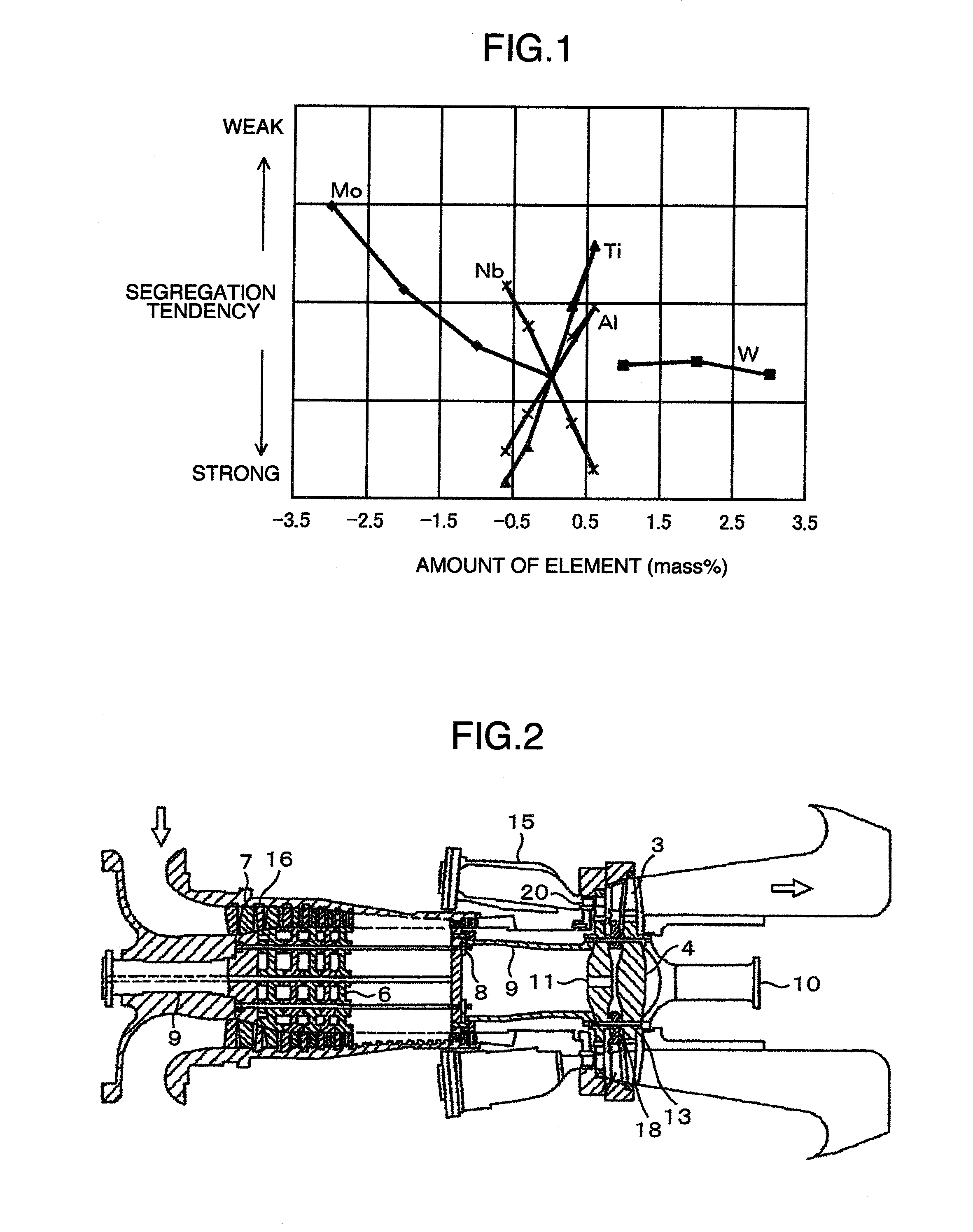
[0006]The inventors examined an influence of each alloy element on a segregation tendency of the alloy by thermodynamics computation, segregation experiment, and the like. As a result, they found that certain additional range of aluminum, titanium, niobium and molybdenum makes an alloy less liable to generate segregation, thereby improving the large-sized steel ingot productivity.
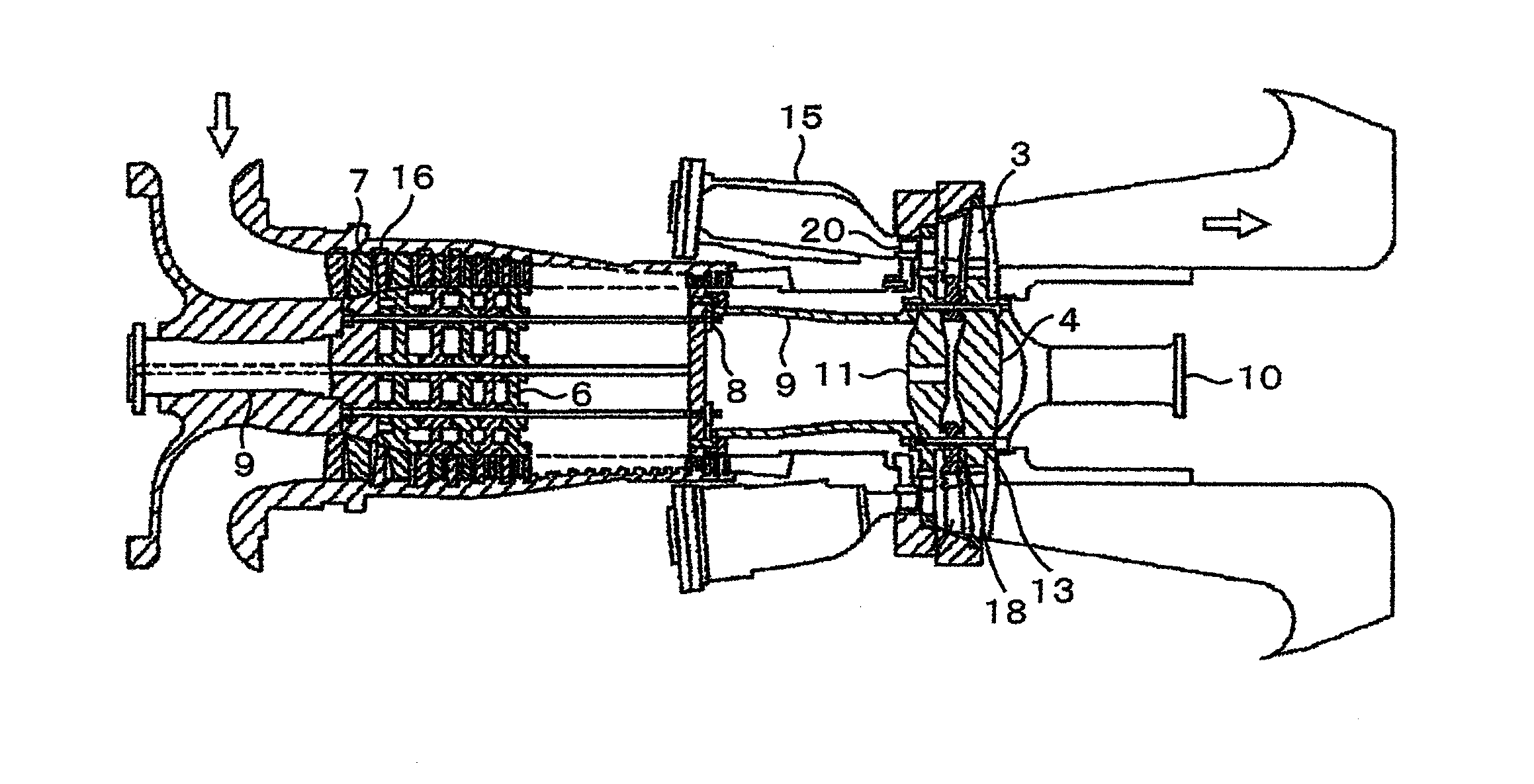
[0009]According to the above, a large-sized component can be manufactured with the Ni-based heat resistant alloy having a high strength, so that the efficiency of a gas turbine can be increased.

Problems solved by technology

The added elements such as titanium, niobium, tantalum or the like are liable to produce segregation during solidification, and thus make it difficult to manufacture a large-sized component.
However, a weight thereof is limited to 2 to 3 tons.
If the product weight exceeds the value, segregation occurs at the time of production, and cracks are undesirably generated at the time of solidification or at the time of forging, so that it is difficult to produce a larger product.
However, Alloy 718 contains large amounts of the above-described precipitation strengthening elements to achieve the higher strength, so that segregation is liable to occur as compared with Alloy 706, and it is difficult to produce a large-sized steel ingot.
Therefore, it is difficult at present to use Alloy 718 for a large-sized gas turbine.

Method used


Image

  • Ni-based heat resistant alloy, gas turbine component and gas turbine
  • Ni-based heat resistant alloy, gas turbine component and gas turbine

Examples


examples

[0027]Hereinafter, examples of the invention are explained.

[0028]Table 1 gives alloy compositions of specimens. Alloys of 10 kg and having compositions in Table 1 were produced in a vacuum induction melting furnace. Nos. 1 to 8 are alloys of the invention (hereinafter, referred to as invention alloys), and Nos. 9 to 11 are comparative alloys. The alloy of No. 9 corresponds to commercially-available Alloy 718. The produced alloys were subjected to removal of oxide film and casting defects from surfaces, and thereafter were hot worked into a round bar shape having 15 mm diameter. From the round-bar stock, various test pieces were taken, and the mechanical properties of the material were evaluated by Vickers hardness test at a room temperature and high-temperature tensile test at 700° C. Also, apart from the 10 kg alloy, a test simulating manufacturing conditions of a large-sized steel ingot was conducted. In the test, presence of segregation was checked, and occurrence tendency of seg...


PUM

PropertyMeasurementUnit
Fractionaaaaaaaaaa
Fractionaaaaaaaaaa
Fractionaaaaaaaaaa

Abstract

A Ni-based heat resistant alloy has a composition of, by mass percent, carbon: 0.001 to 0.1%, chromium: 16 to 22%, aluminum: 0.5 to 1.5%, molybdenum: 0.1 to 2.0%, tungsten: 0.1 to 6.0%, niobium: 3.5 to 5.5%, titanium: 0.8 to 3.0%, iron: 16 to 20%, and the balance being nickel and inevitable impurities. A parameter Ps indicating a segregation tendency is in a range of Ps≧−3.5. The parameter Ps is represented by Formula (1).Ps=1.05×Al content+0.6×Ti content−0.8×Nb content−0.3×Mo content  (1)

Description

FIELD OF THE INVENTION[0001]The present invention relates to a Ni-based heat resistant alloy having improved segregation properties and capable of being applied to large-sized components. The invention also relates to a gas turbine component including the alloy, and a gas turbine.BACKGROUND OF THE INVENTION[0002]It is effective to rise a combustion temperature for increasing an efficiency of a gas turbine. Therefore, a Ni-based heat resistant alloy having high-temperature strength is employed for various parts in components for the gas turbine. The Ni-based alloy contains large amounts of solid-solution strengthening elements such as tungsten, molybdenum or cobalt and precipitation strengthening elements such as aluminum, titanium, niobium or tantalum, and therefore has excellent high-temperature strength. A γ′ phase (Ni3Al) is a main precipitation strengthening phase, and the strength thereof increases depending on an increase of its temperature. Thus, the γ′ phase is very effectiv...

Claims


Application Information

Patent Timeline
IPC IPC(8): F01D5/00C22C19/05
CPCC22C19/05C22F1/10Y02E20/16F01D5/28F01D5/30C22C19/056
Inventor SATO, JUNIMANO, SHINYADOI, HIROYUKI
Owner MITSUBISHI POWER LTD
Learn More