Magneto-resistive effect element having spacer layer including main spacer layer containing gallium oxide and nonmagnetic layer

a technology of magnetoresistive effect and main spacer layer, which is applied in the field of magnetoresistive effect element configuration, can solve the problems of reducing the mr ratio, oxidizing the ferromagnetic layer, and the potential for a more prominent decrease in the mr ratio

Active Publication Date: 2012-06-28
TDK CORPARATION
View PDF6 Cites 4 Cited by
  • Summary
  • Abstract
  • Description
  • Claims
  • Application Information

AI Technical Summary

Benefits of technology

[0010]An MR element of the present invention includes first and second magnetic layers of which relative angles formed by magnetization directions change in relation to an external magnetic field; and a spacer layer positioned between the first magnetic layer and the second magnetic layer. The first magnetic layer is positioned on a side closer than the second magnetic layer in regards to a substrate above which the magnetoresistive effect element is formed, and the spacer layer includes a main spacer layer made of gallium oxide as the primary component, and a first nonmagnetic layer positioned between the main spacer layer and the first magnetic layer and contains copper and gallium.

Problems solved by technology

The ferromagnetic layer adjacent to the spacer layer is generally composed of Co, Ni, Fe, or the like as a primary component as described above; and, there is a problem in that when these elements are arranged to contact gallium oxide, the ferromagnetic layer is oxidized by the oxidative effect of oxygen contained in the gallium oxide which reduces the MR ratio.
In addition, the MR element may go through a heating process after a laminated film is formed, and in that case, there is potential for a more prominent decrease in the MR ratio due to oxidation of the magnetic layer.

Method used


Image

  • Magneto-resistive effect element having spacer layer including main spacer layer containing gallium oxide and nonmagnetic layer
  • Magneto-resistive effect element having spacer layer including main spacer layer containing gallium oxide and nonmagnetic layer
  • Magneto-resistive effect element having spacer layer including main spacer layer containing gallium oxide and nonmagnetic layer

Examples


first embodiment

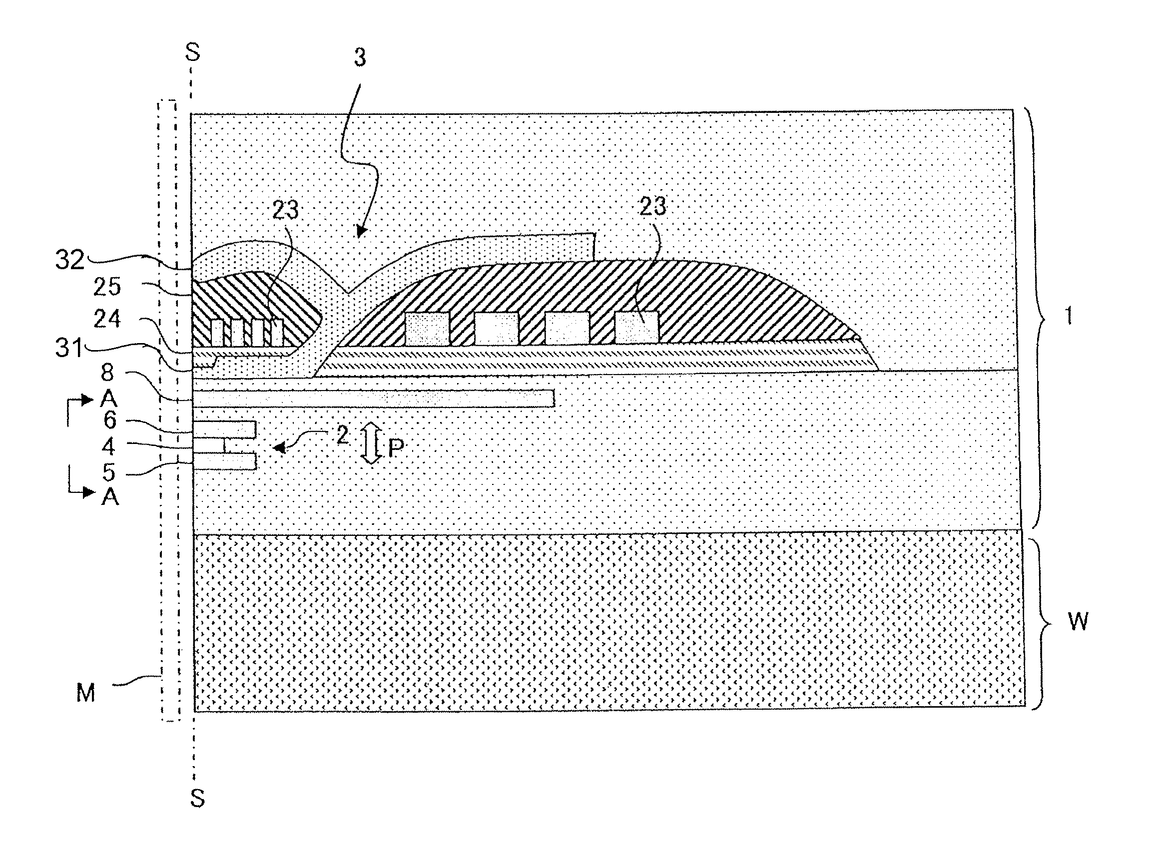
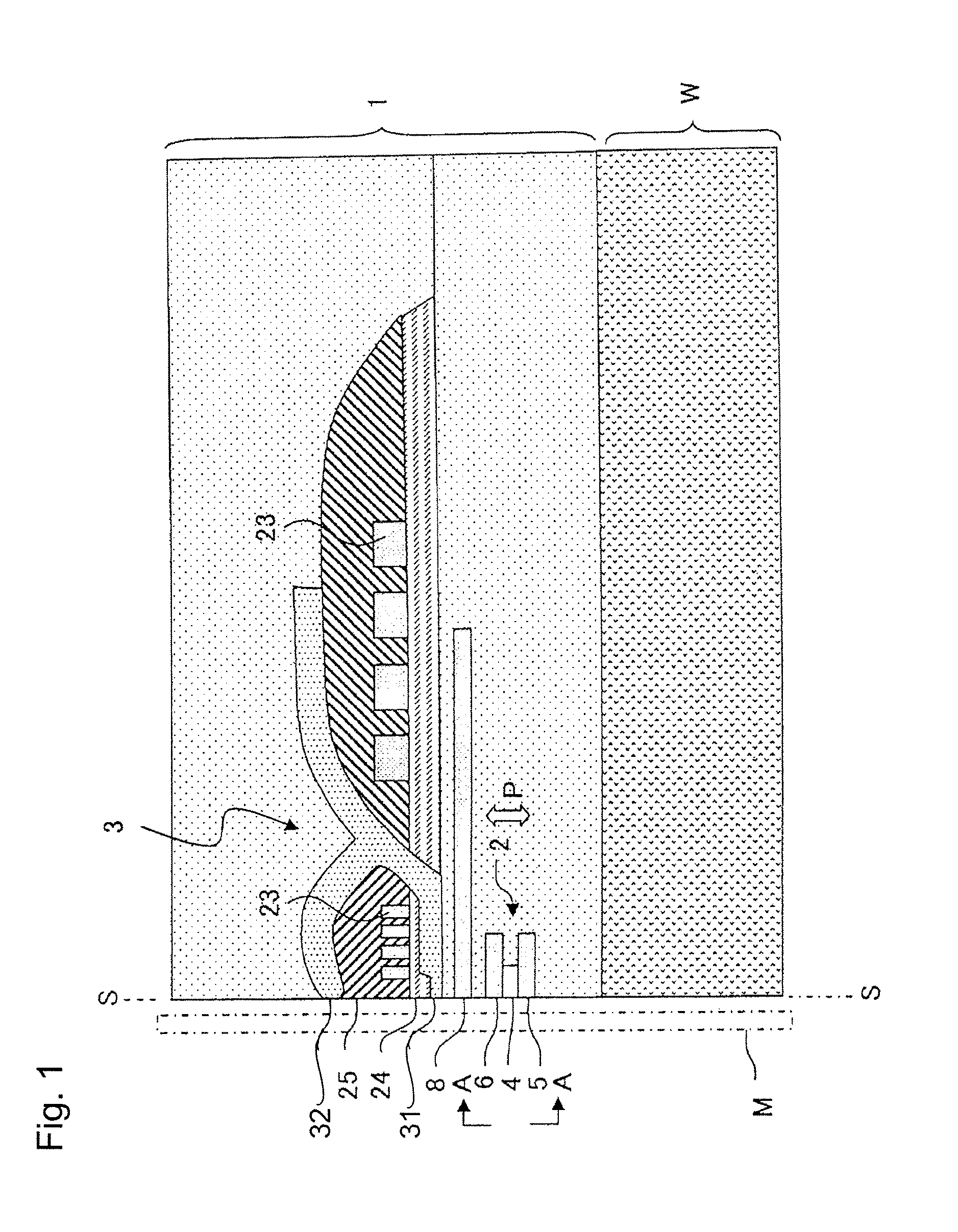
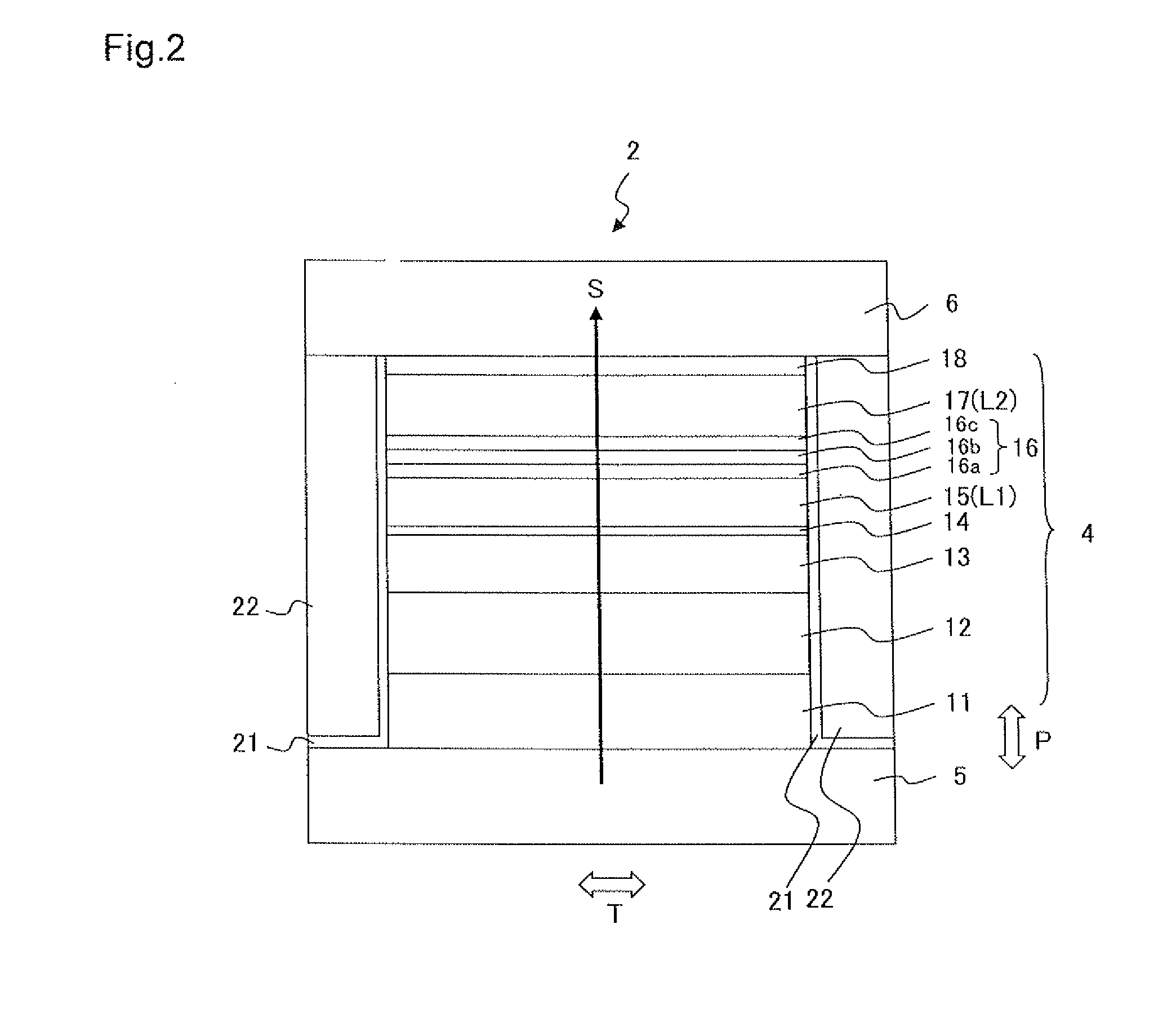
[0024]FIG. 1 illustrates a main part cross-sectional view of a thin film magnetic head 1 that relates to a first embodiment. The thin film magnetic head 1 is formed on a substrate W and includes a reproducing head 2 and a recording head 3. FIG. 2 is a side view of the reproducing head 2 as viewed from the A-A direction of FIG. 1 and illustrates the layer configuration of the reproducing head 2 on the air bearing surface S. The air bearing surface S is a surface of the thin film magnetic head 1 that opposes the recording medium M. An initial description will be given of the configuration of the reproducing head 2 with reference to FIG. 2.

[0025]The reproducing head 2 includes a spin valve type MR element 4, upper and lower shield layers 6 and 5 disposed so as to sandwich the MR element 4 in a film surface orthogonal direction (lamination direction) P, and bias magnetic field application layers 22 disposed on both sides of the MR element 4 in the track width direction T (paper surface ...

second embodiment

[0042]A thin film magnetic head 1 of the present embodiment is the same as the first embodiment indicated in FIG. 1 with the exception of the configuration of the reproducing head 2. The layer configuration of the MR element is indicated in FIG. 4 and Table 2. A reproducing head 102 includes an MR element 104 in which a plurality of layers are laminated in the same manner as in the first embodiment, and upper and lower shield layers 106 and 105 that are disposed so as to sandwich the MR element 104 in the film surface orthogonal direction P (lamination direction). The upper and lower shield layers 106 and 105 are also used as electrodes for the sense current S to flow sense current S in the film surface orthogonal direction P of the MR element 104.

[0043]With the present embodiment, a first magnetic layer L1 and a second magnetic layer L2 are respectively magnetization free layers 115 and 117 of which the magnetization directions changes in relation to the external magnetic field. Th...

example

[0052]The magnetoresistive effect film with the layer configuration indicated in Table 2 was formed on the substrate W made of Al2O3—TiC (ALTIC) using a radio frequency (RF) sputtering device. After film formation, heat treatment was performed for three hours at 250° C. The first and second magnetization free layers 115 and 117 are oriented in mutually orthogonal directions when there is no external magnetic field; however, they rotate freely when an external magnetic field is applied thereby generating a magnetoresistive effect.

[0053]The MR ratio was evaluated by changing the material and film thickness of the first nonmagnetic layer 116a in this multilayer film. Cu was used for the second nonmagnetic layer 116c. Table 4 illustrates MR ratios normalized by the MR ratio being set to 1 when a Ga40Cu60 alloy (film thickness 0.6 nm) is used as the first nonmagnetic layer 116a. The description of Ga x Cu (100-x) (when x is an integer between 0 and 100) indicates that the atomic percent ...


PUM

PropertyMeasurementUnit
thicknessaaaaaaaaaa
thicknessaaaaaaaaaa
mole fractionaaaaaaaaaa

Abstract

A magnetoresistive effect element (MR element) includes first and second magnetic layers of which relative angles formed by magnetization directions change in relation to an external magnetic field; and a spacer layer positioned between the first magnetic layer and the second magnetic layer. The first magnetic layer is positioned on a side closer than the second magnetic layer in regards to a substrate above which the magnetoresistive effect element is formed, and the spacer layer includes a main spacer layer made of gallium oxide as the primary component, and a first nonmagnetic layer positioned between the main spacer layer and the first magnetic layer and contains copper and gallium.

Description

BACKGROUND OF THE INVENTION[0001]1. Field of the Invention[0002]The present invention relates to a magnetoresistive effect element (MR element) and particularly relates to a configuration of a spacer layer.[0003]2. Description of the Related Art[0004]Reproducing heads having high sensitivity and high output are in demand in conjunction with condensing of high recording density in hard disk drives (HDD). A spin valve head has been developed as an example of this type of reproducing head. A spin valve head includes a nonmagnetic metal layer and a pair of ferromagnetic layers positioned to contact both sides of the nonmagnetic metal layer. The magnetization direction of one side of the ferromagnetic layers is pinned in one direction (hereinafter, this type of layer is referred to as a magnetization pinned layer), and the magnetization direction of the other side of the ferromagnetic layers freely rotates in response to an external magnetic field (hereinafter, this type of layer is refe...

Claims


Application Information

Patent Timeline
Patent Type & Authority Applications(United States)
IPC IPC(8): G11B5/39
CPCB82Y10/00B82Y25/00Y10T428/1121G11B5/3929G11B2005/3996G11B5/3909
Inventor CHOU, TSUTOMUTSUCHIYA, YOSHIHIROMATSUZAWA, HIRONOBUKOIKE, HAYATO
Owner TDK CORPARATION
Why Eureka
Try Eureka