
Method and system for cleaning of and heat recovery from hot gases

a technology of hot gas and heat recovery, which is applied in the direction of electrical equipment, electrochemical generators, lighting and heating equipment, etc., can solve the problems of cyclones and scrubbers being less effective, thermal reactors having restrictions on the type of fuel to be used, and waste of heat energy of gas

Inactive Publication Date: 2012-07-05
DALL ENERGY HLDG
View PDF0 Cites 10 Cited by
  • Summary
  • Abstract
  • Description
  • Claims
  • Application Information

AI Technical Summary

Benefits of technology

[0099]In accordance with the present invention one or several hydro cyclones may be placed upstream to the heat exchanger which cools the condensate from the quench and / or the gas scrubber. Hereby the lifetime of the heat exchanger will be extended considerably and the cleaning efficiency of the scrubber will be increased.
[0105]When primary air for the solid fuel conversion is used as gasification agent a high load of water vapours is a great advantage in order to prevent slagging and in order to enhance H2 production in the gasifier.
[0112]The present invention may provide clean water for the gas cooler and air moisturiser and a clean cold gas of the gas cooler.
[0115]A further advantage of such system may be that the overall system efficiency can be improved as more heat may be produced in connection with the condensing gas cooler, as the gasification air is moisturised.
[0117]As indicated above, various aspects of the present invention may offer a number of advantages compared to state-of-the-art combustion technologies. It could therefore be expected that various aspects of the invention will be expensive and complicated. However, the simplicity and the compactness of the system may be seen as a main advantage of the invention.

Problems solved by technology

The water is usually heated in a closed circuit and led to a point of consumption, after which the water is returned to the heat production unit after release of the thermal energy.
The restriction to cool the gas is normally:The temperature of the return water of the district heating networkOutdoor air, and in this case the heat energy of the gas is wasted.
But thermal reactors have restrictions on the type of fuel to be used.
Especially bag filters and electrostatic filters are very effective towards particulate filtration, whereas cyclones and scrubbers typically are less effective, but also normally cheaper.
When scrubber water is not regularly cleaned, the particle and salt content may become rather high, and the scrubber water may cause re-entrainment of contaminants into the gas.
When scrubber water is loaded with particles the scrubber-district heating heat exchanger may have a short lifetime as coarse particles erode the heat exchanger.
Hydro cyclones are not used in condensing scrubbers as the water fractions with the high particle load needs further filtration, and therefore are the hydrocylone not cost efficient.

Method used


Image

  • Method and system for cleaning of and heat recovery from hot gases
  • Method and system for cleaning of and heat recovery from hot gases
  • Method and system for cleaning of and heat recovery from hot gases

Examples


Embodiment Construction

[0082]The present invention provides inter alia an improved method and an improved system or installation for thermal conversion of solid fuels into energy, hereof at least part of the energy as hot water.

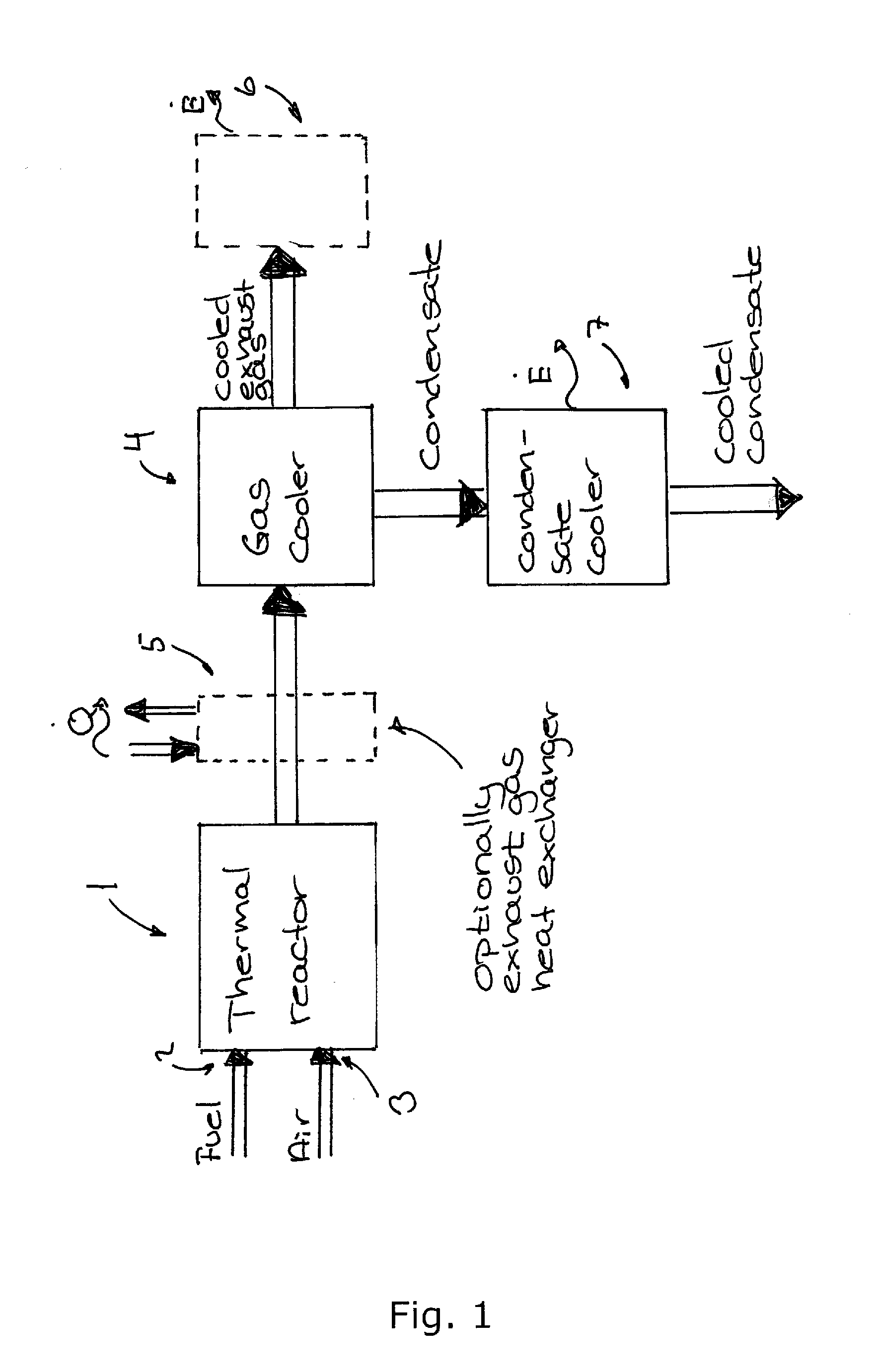
[0083]In a first aspect the present invention relates to a thermal plant comprising[0084]a thermal reactor in which a chemical process takes place during which process solid fuels reacts with oxygen to produce an exhaust gas comprising hot flue gas and / or a burnable gas[0085]a gas cooler cooling the exhaust gas to a temperature below the dew point of the water present in the exhaust gas thereby producing a condensate;[0086]a condensate cooler cooling the condensate to extract energy from the condensate.

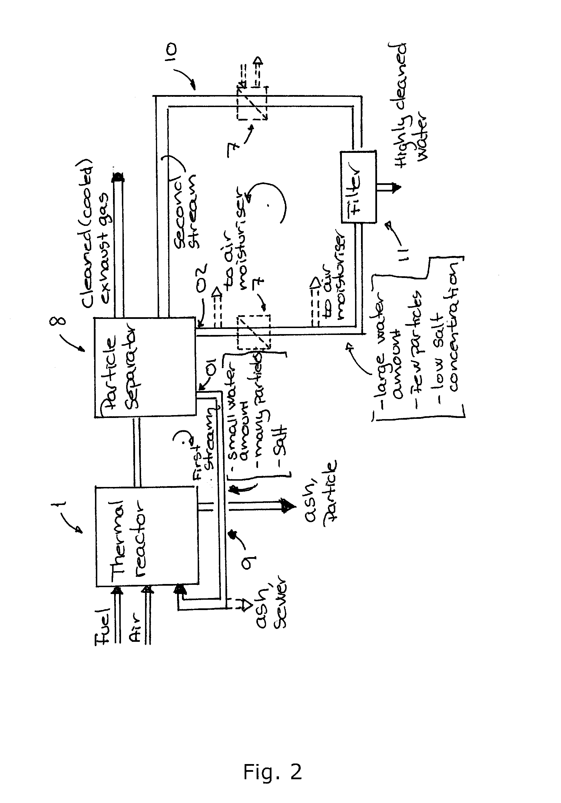
[0087]The present invention further relates inter alia to a particle separation system of a a thermal plant according to the invention into which particle separator a stream of fluid (gas and / or liquid) which contain particles enters and where at least two streams of water are produc...


PUM

PropertyMeasurementUnit
temperatureaaaaaaaaaa

Abstract

Exhaust gas, produced in a thermal reactor (1) that is fed with solid fuel can be cooled and in a gas cooler (4) which produce a condensate that is further cooled in a condensate cooler (7) which produce energy. By using air moisturizing and particle separation technology the exhaust gas and the excess condensate can be clean and the energy efficiency of the plant can be increased. The method can be used for a broad spectrum of fuels and conversion technologies.

Description

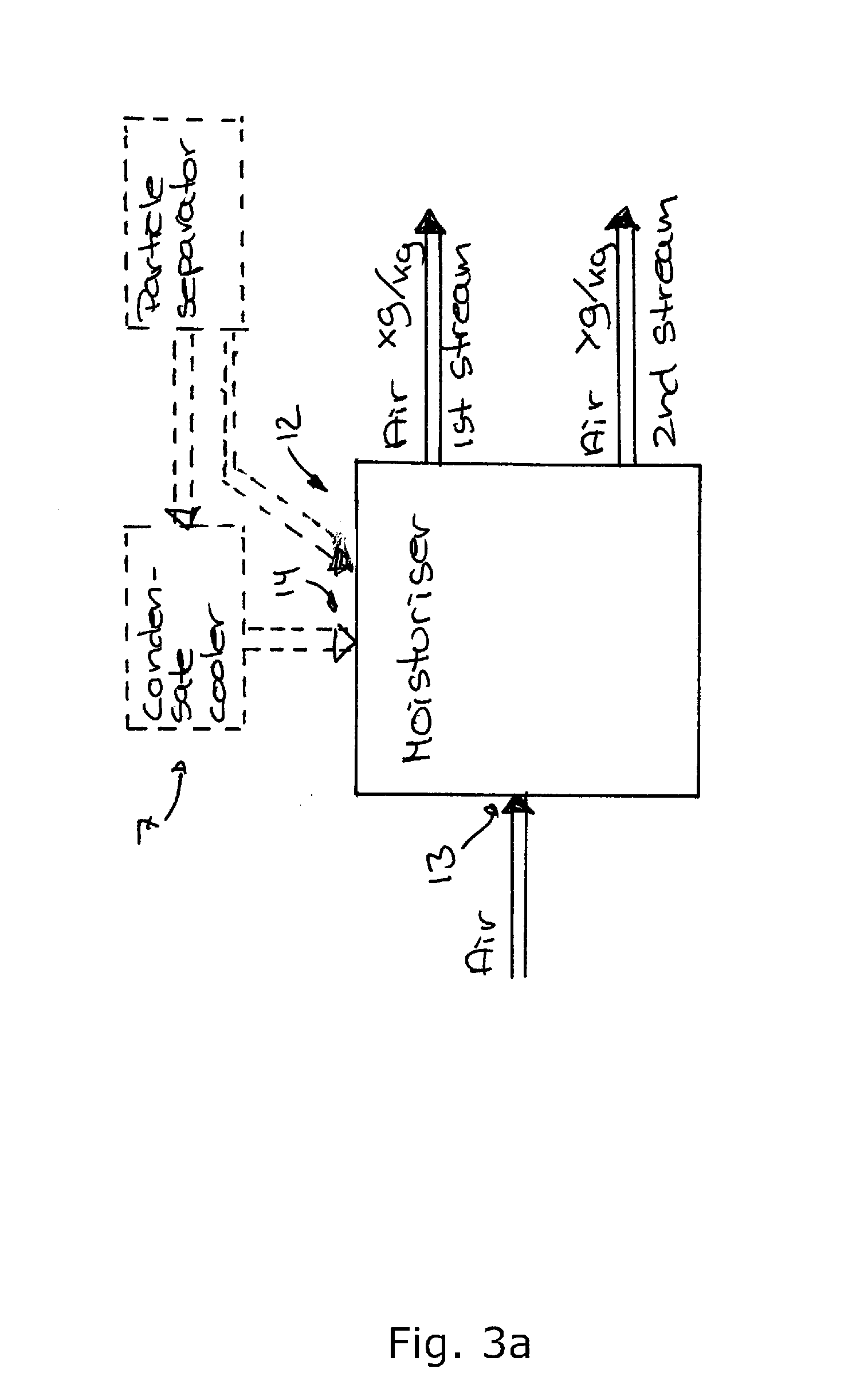
[0001]This invention relates inter alia to a method and a system for cleaning of and heat recovery from hot gases, e.g. flue gas, produced in a thermal reactor, or—more specific—using water to cool and clean gases, released by thermal conversion (gasification or combustion) of fuels e.g. biomass, waste, coal, oils, gases or mixtures of these, by having three process steps:[0002]Removal of contaminants (particles, salts, acids etc.) from gas in a water based scrubber;[0003]Removal of contaminants of the scrubber water by use of centrifuges and / or hydro cyclones;[0004]Heat recovery of the energy obtained in the scrubber water.[0005]Furthermore, the invention relates to methods and systems for[0006]Moisturizing the air for a thermal reactor in two moisturisers[0007]Removal of particles in the scrubber water[0008]Recirculation of particles from the scrubber to the fuel system.[0009]In an overall perspective, the invention may be seen as relating to handle particles in water which partic...

Claims


Application Information

Patent Timeline
Patent Type & Authority Applications(United States)
IPC IPC(8): C10J3/48
CPCB01D47/00F22B37/008C10J3/84C10J3/86F23J15/022F23J15/027F23J15/04F23J15/06F23J2219/40F23J2219/70Y02E20/363C10K1/02C10K1/06C10K1/101C10J2300/0956C10J2300/0973C10J2300/0976C10J2300/169C10J2300/1884F01K13/00B01D2247/04Y02E20/30Y02P20/10Y02P20/50Y02P70/10
Inventor BENTZEN, JENS DALL
Owner DALL ENERGY HLDG
Learn More