Cleaning device and a cleaning method of a fixed abrasives polishing pad

a polishing pad and cleaning device technology, applied in the direction of grinding drives, abrasive surface conditioning devices, manufacturing tools, etc., can solve the problems of affecting the polishing rate, scratching the workpiece, surface irregularities of the wafer, etc., to reduce the scratching of the workpiece, improve the yield and production efficiency

Active Publication Date: 2012-07-05
SEMICON MFG INT (SHANGHAI) CORP
View PDF5 Cites 9 Cited by
  • Summary
  • Abstract
  • Description
  • Claims
  • Application Information

AI Technical Summary

Benefits of technology

[0023]Compared with the prior art, the technical solution provided by the present invention can effectively reduce scratching of a work piece in the process of the fixed abrasive chemical mechanical polishing, and improve the yield and production efficiency.

Problems solved by technology

As the number of layers increases, surface irregularities of the wafer will be a problem for acceptable yield and long-term reliability of a chip.
The principle of a fixed abrasives chemical mechanical polishing is two-body abrasion, that is, a work piece is polished by abrasives fixed on a polishing pad, with an inevitable consequence, that some byproducts of micro particles during polishing such as some dropped fixed abrasive particles in operation, if not cleared away, not only affect the polishing rate, but also scratch the work piece, then affect the polishing precision and yield.
Although a part of the polishing byproducts may be removed through this technique, this technique has low efficiency and is limited to cleaning capability for low particles precision on the caterpillar and is easily polluted by the byproducts, so the technique may not be suitable to be used as the cleaning device.
Although this disclosure improves cleaning efficiency, the micro particles remained on the surface of the polishing pad cannot be removed in time by simply cleaning using pressure, and scratching of a work piece cannot be avoided as the byproducts may migrate to the polishing interface.
However, a homogeneous hydraulic pressure of the cleaning liquid is difficult to be maintained throughout the polishing pad.
For example, the washing pressure in the region of the polishing pad which is more distant from the nozzle is weak relatively to the washing pressure in the region close to the nozzle; the conventional system may not ensure that micro byproducts can be effectively removed.

Method used


Image

  • Cleaning device and a cleaning method of a fixed abrasives polishing pad
  • Cleaning device and a cleaning method of a fixed abrasives polishing pad
  • Cleaning device and a cleaning method of a fixed abrasives polishing pad

Examples


Embodiment Construction

[0028]Hereunder, the present invention will be described in detail with reference to embodiments, in conjunction with the accompanying drawings.

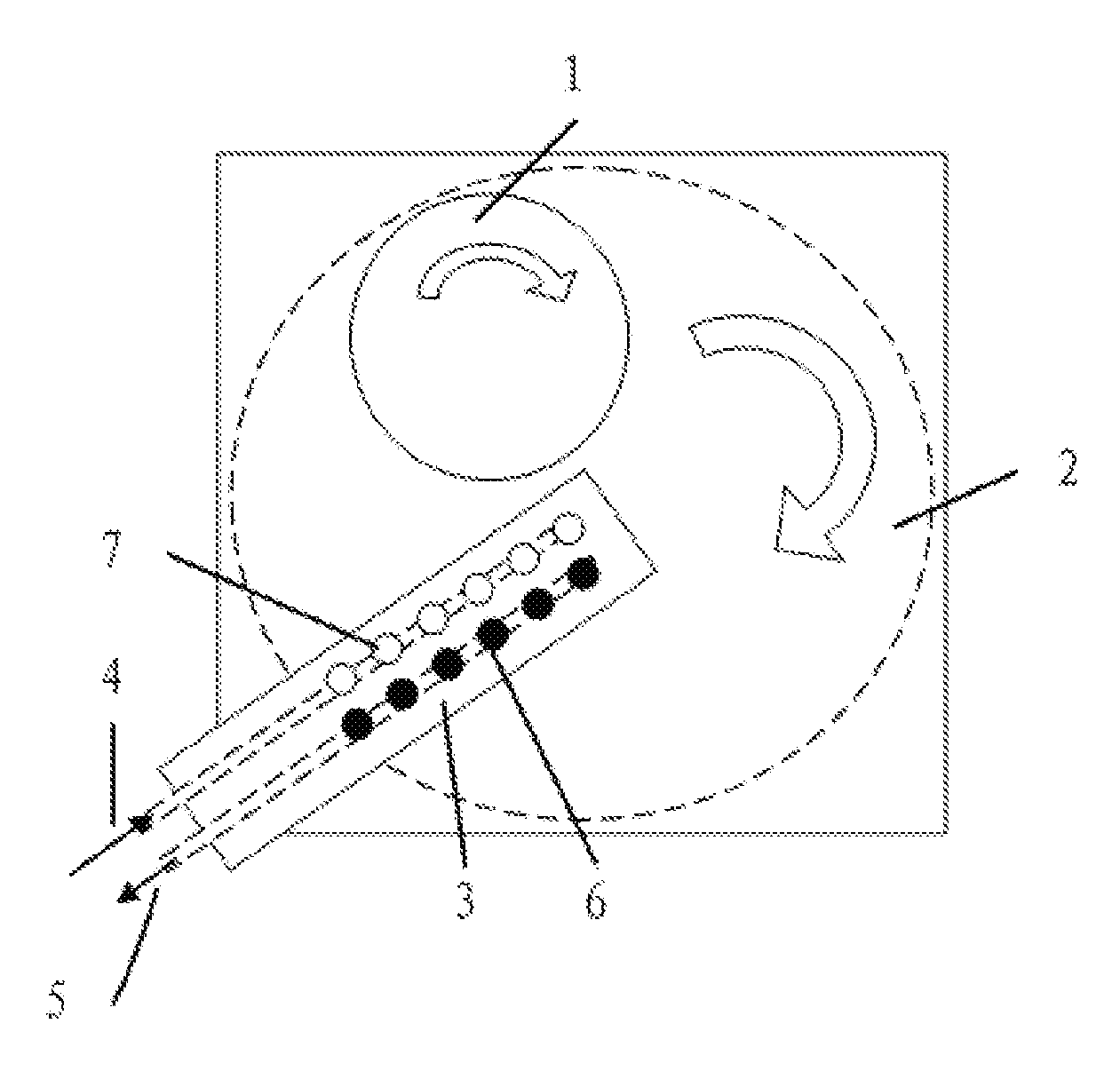
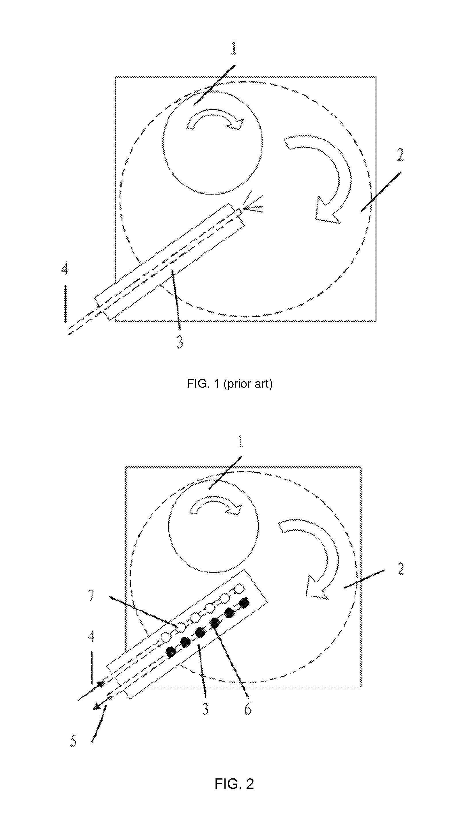
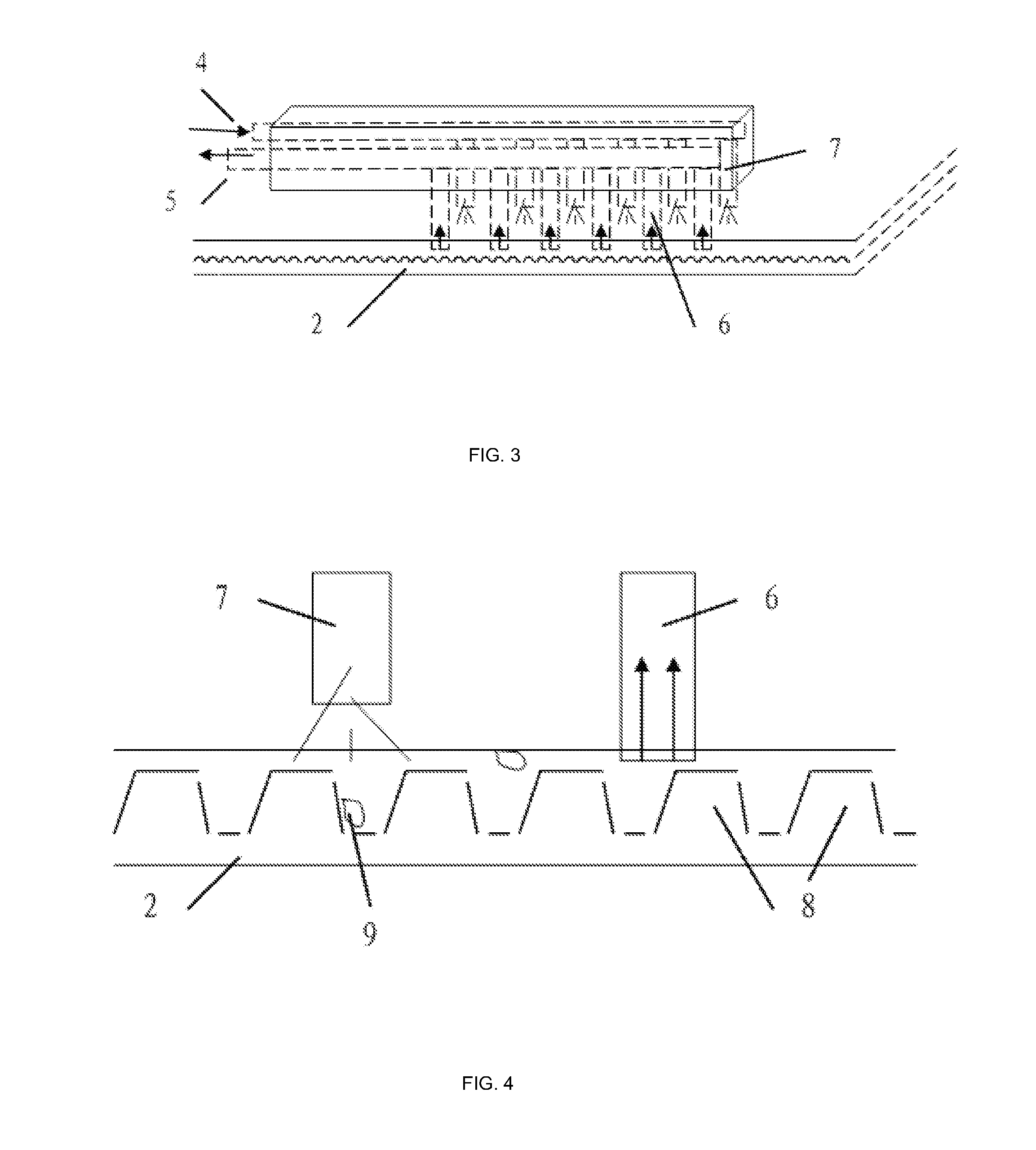
[0029]A fixed abrasives chemical mechanical polishing technology developed on the base of these includes a rotary device for fixing a wafer (“chuck”), a polishing table for holding a polishing pad and a cleaning system. As fixed abrasives on a polishing pad replace free abrasives, the supply system for supplying polishing liquid is omitted. A basic structure of the polishing pad is similar to a structure of sand paper. The polishing pad of composite construction is formed by using resin binder to cohere submicron abrasives or nano-abrasives to form fine particles in a particular shape of three dimensional structure (about tens micrometers to hundreds micrometers in length and width, about tens micrometers in height) and accurately bonding the fine particles on a polymeric substrate. The fixed abrasives polishing pad replaces the free abrasiv...


PUM


Abstract

A device for cleaning a fixed abrasive polishing pad includes a main body having a surface facing the polishing pad, an inlet coupled to an end of the main body and configured to supply a cleaning liquid, an inject orifice coupled to the inlet for injecting the cleaning liquid and being provided on the surface of the main body, an outlet coupled to the end of the main body, and a recycle orifice coupled to the outlet, and being provided on the surface of the main body.

Description

CROSS-REFERENCES TO RELATED APPLICATIONS[0001]The present application claims the priority of Chinese Patent Application No 201010613438.9, entitled “A Cleaning Device And A Cleaning Method Of A Fixed Abrasives Polishing Pad”, and filed on Dec. 29, 2010, the entire disclosure of which is incorporated herein by reference.BACKGROUND OF THE INVENTION[0002]1. Field of the Invention[0003]This invention relates to chemical mechanical polishing in semiconductor fabrication, and more particularly, to cleaning of a fixed abrasive polishing pad.[0004]2. Description of Prior Art[0005]Current processing of semiconductor wafers includes deposition of several layers containing a plurality of patterns and vertically interconnected elements for forming an integrated circuit (IC) device. A typical integrated circuit may have six or more layers of metal wiring that are isolated by interlayer dielectric layers. As the number of layers increases, surface irregularities of the wafer will be a problem for...

Claims


Application Information

Patent Timeline
Patent Type & Authority Applications(United States)
IPC IPC(8): B08B7/00B24B55/00
CPCB24B53/017B24B37/245
Inventor CHEN, FENG
Owner SEMICON MFG INT (SHANGHAI) CORP
Why Eureka
Try Eureka