
Method of Isolating the Cerebral Circulation During a Cardiac Procedure

a technology of cerebral circulation and cardiac procedure, applied in the field of blood filtering methods and equipment, can solve the problems of tissue ischemia (lack of oxygen and nutrients), death, myocardial infarction, stroke, etc., and achieve the effect of increasing the level of particulate protection

Active Publication Date: 2012-07-05
BOSTON SCI SCIMED INC
View PDF3 Cites 42 Cited by
  • Summary
  • Abstract
  • Description
  • Claims
  • Application Information

AI Technical Summary

Benefits of technology

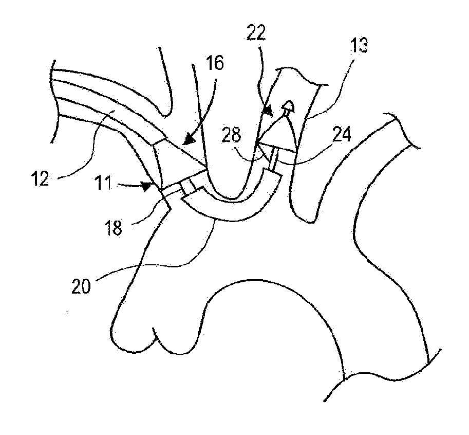
[0016]One aspect of the disclosure is a catheter-based endovascular system and method of use for filtering blood that captures and removes particles caused as a result of a surgical or endovascular procedures. The method and system include a first filter placed in a first vessel within the patient's vascular system and a second filter placed in a second vessel within the patient's vascular system. In this manner, the level of particulate protection is thereby increased.
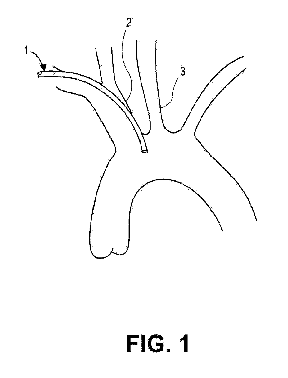
[0017]One aspect of the disclosure is an endovascular filtration system and method of filtering blood that protects the cerebral vasculature from embolisms instigated or foreign bodies dislodged during a surgical procedure. In this aspect, the catheter-based filtration system is disposed at a location in the patient's arterial system between the site of the surgical procedure and the cerebral vasculature. The catheter-based filtration system is inserted and deployed at the site to capture embolisms and other foreign bodies and prevent their travel to the patient's cerebral vasculature so as to avoid or minimize thromboembolic disorders such as a stroke.
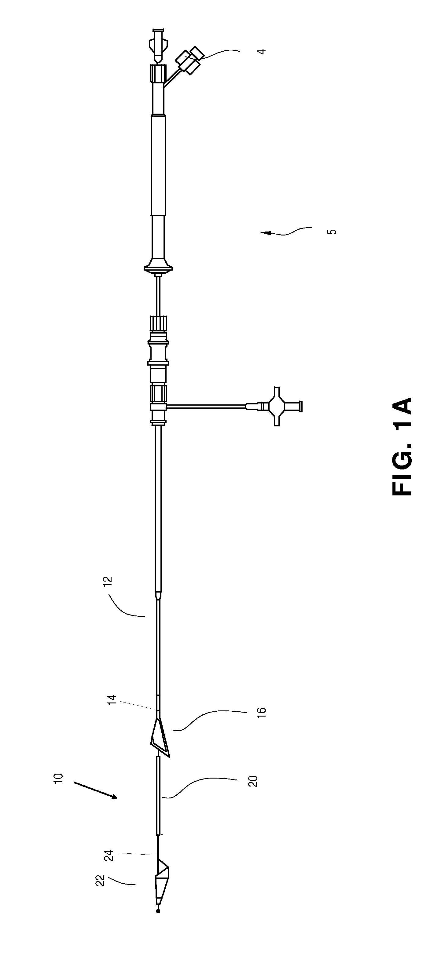
[0021]In some aspects of the disclosure, the second filter is carried on a guiding member having a guidewire lumen extending therethrough. In certain aspects, the guiding member is a catheter shaft. A guiding member having a guidewire lumen allows the user to precisely deliver the second filter by advancing the filter system over the guidewire. The guiding member can be configured to have increased column strength to aid advancement of the second filter. In some aspects, the guiding member includes a flexible portion to better position the second filter within the vessel.
[0022]In some aspects the first sheath is a proximal sheath, the first filter is a proximal filter, the second sheath is a distal sheath, and the second filter is a distal filter. The proximal sheath is provided with a proximal hub housed within and in sliding engagement with the handle. Movement of the proximal hub causes translation of the proximal sheath relative to the proximal filter. The distal sheath includes a distal shaft section and a distal articulatable sheath section. A wire is provided from the handle to the distal articulatable sheath section. Manipulation of the handle places tension on the wire causing the distal articulatable sheath section to articulate from a first configuration to one or more other configurations. The articulatable distal sheath is capable of rotation, translation, and deflection (both in a single plane and both partially in a first plane and partially in a second, different plane). In some embodiments, the handle includes a locking mechanism to prevent the articulatable distal sheath from deviating from a desired configuration. In certain embodiments, the locking mechanism may lock automatically when the operator actuates a control or releases the handle.
[0023]In some aspects the proximal filter and the distal filter are both self-expanding. The proximal filter and the distal filter both may comprise an oblique truncated cone shape. Movement of the proximal sheath relative to the proximal filter causes the proximal filter to expand and deploy against the inside wall of a first vessel. The distal filter is then advanced through or adjacent to the distal shaft and distal articulatable sheath into expanding engagement against the inner wall of a second vessel. In some embodiments, a tethering member extends from the proximal sheath to the proximal filter to help draw the proximal filter opening toward the first vessel wall.

Problems solved by technology

These disorders are a major cause of morbidity and mortality in the United States and throughout the world.
When an artery is occluded by a clot or other embolic material, tissue ischemia (lack of oxygen and nutrients) develops.
Failure to reestablish blood-flow can lead to the loss of limb, angina pectoris, myocardial infarction, stroke, or even death.
Occlusion of the venous circulation by thrombi leads to blood stasis which can cause numerous problems.
While such surgical techniques have been useful, exposing a patient to surgery may be traumatic and is best avoided when possible.
Additionally, the use of a Fogarty catheter may be problematic due to the possible risk of damaging the interior lining of the vessel as the catheter is being withdrawn.
Balloon angioplasty is appropriate for treating vessel stenosis but is generally not effective for treating acute thromboembolisms.
Unfortunately, thrombolysis typically takes hours or days to be successful.
Additionally, thrombolytic agents can cause hemorrhage and in many patients the agents cannot be used at all.
Another problematic area is the removal of foreign bodies.
The use of such removal devices can be difficult and sometimes unsuccessful.
Moreover, systems heretofore disclosed in the art are generally limited by size compatibility and the increase in vessel size as the emboli is drawn out from the distal vascular occlusion location to a more proximal location near the heart.
If the embolectomy device is too large for the vessel it will not deploy correctly to capture the clot or foreign body, and if too small in diameter it cannot capture clots or foreign bodies across the entire cross section of the blood vessel.
Additionally, if the embolectomy device is too small in retaining volume then as the device is retracted the excess material being removed can spill out and be carried by flow back to occlude another vessel downstream.
Such devices, however, have been found to have structures which are either highly complex or lacking in sufficient retaining structure.
Disadvantages associated with the devices having highly complex structure include difficulty in manufacturability as well as difficulty in use in conjunction with microcatheters.
Additionally, due to difficult-to-access anatomy such as the cerebral vasculature and the neurovasculature, the systems should have a small collapsed profile.
The risk of dislodging foreign bodies is also prevalent in certain surgical procedures.

Method used


Image

  • Method of Isolating the Cerebral Circulation During a Cardiac Procedure
  • Method of Isolating the Cerebral Circulation During a Cardiac Procedure
  • Method of Isolating the Cerebral Circulation During a Cardiac Procedure

Examples


Embodiment Construction

[0070]Although certain preferred embodiments and examples are disclosed below, inventive subject matter extends beyond the specifically disclosed embodiments to other alternative embodiments and / or uses, and to modifications and equivalents thereof. Thus, the scope of the claims appended hereto is not limited by any of the particular embodiments described below. For example, in any method or process disclosed herein, the acts or operations of the method or process can be performed in any suitable sequence and are not necessarily limited to any particular disclosed sequence. Various operations can be described as multiple discrete operations in turn, in a manner that can be helpful in understanding certain embodiments; however, the order of description should not be construed to imply that these operations are order dependent. Additionally, the structures described herein can be embodied as integrated components or as separate components. For purposes of comparing various embodiments...


PUM


Abstract

Single filter and multi-filter endolumenal methods and systems for filtering fluids within the body. In some embodiments a blood filtering system captures and removes particulates dislodged or generated during a surgical procedure and circulating in a patient's vasculature. In some embodiments a filter system protects the cerebral vasculature during a cardiac valve repair or replacement procedure.

Description

CROSS-REFERENCE TO RELATED APPLICATIONS[0001]This application claims the priority benefit under 35 U.S.C. §119(e) of U.S. Provisional Application No. 61 / 428,653, filed Dec. 30, 2010; U.S. Provisional Application No. 61 / 493,447, filed Jun. 4, 2011; U.S. Provisional Application No. 61 / 550,889, filed Oct. 24, 2011; and U.S. Provisional Application No. 61 / 556,142, filed Nov. 4, 2011, the entire contents of which are hereby incorporated by reference and should be considered a part of this specification.BACKGROUND OF THE INVENTION[0002]1. Field of the Invention[0003]In general, the disclosure relates to methods and apparatuses for filtering blood. The filtration systems can be catheter-based for insertion into a patient's vascular system.[0004]2. Description of the Related Art[0005]Thromboembolic disorders, such as stroke, pulmonary embolism, peripheral thrombosis, atherosclerosis, and the like, affect many people. These disorders are a major cause of morbidity and mortality in the United...

Claims


Application Information

Patent Timeline
Patent Type & Authority Applications(United States)
IPC IPC(8): A61M29/00
CPCA61F2230/008A61F2230/0067A61F2230/0008A61F2/013A61F2002/018A61F2250/0029A61F2002/016A61F2002/015A61F2230/0093A61F2210/0014A61F2230/0006A61F2230/005A61F2/012A61B17/22031A61F2/2427A61F2/011
Inventor FIFER, DANIEL W.LASHINSKI, RANDALL T.FIELDS, ANTONY J.LEE, MICHAEL
Owner BOSTON SCI SCIMED INC
Learn More