
Pre-Sressed Insulated Tubing

a technology of insulated tubing and pre-stressed insulating tubing, which is applied in the direction of insulation, mechanical equipment, and borehole/well accessories, etc., can solve the problems of reducing the vacuum degree in the cavity, destroying the insulating system and reducing the insulating performance of pre-stressed insulated tubing. , to achieve the effect of reducing thermal loss, improving insulating performan

Active Publication Date: 2012-07-12
CNPC BOHAI EQUIP MFG
View PDF7 Cites 19 Cited by
  • Summary
  • Abstract
  • Description
  • Claims
  • Application Information

AI Technical Summary

Benefits of technology

[0019]The advantageous effects of the present invention are as follows: the present invention proposes the above-mentioned technical solutions of the pre-stressed insulated tubing, the insulated casing is provided between the inner tube and the outer tube and consists of several concentric tubes (steel tubes), and the annular space between the concentric tubes is vacuumized and added with getter. So compared with the traditional insulated tubing, the vacuum degree of the pre-stressed insulated tubing of the present invention is higher. Except for the outer concentric tube, outer walls of other concentric tubes are wound around with the metal foils, which can enhance the insulating effect and make the insulating performance better (generally, an insulated casing with three concentric tubes can achieve the vacuum degree of not larger than 0.1 Pa, insulating level E and apparent heat-conduction coefficient in the range of 0.006-0.002 w / m° C.), can satisfy special well situations which demand for higher insulating level and less thermal loss, and can prolong the working life of the pre-stressed insulated tubing considerably. In addition, the insulated casing in the pre-stressed insulated tubing of the present invention is reusable, thereby saving cost effectively.
of the present invention are as follows: the present invention proposes the above-mentioned technical solutions of the pre-stressed insulated tubing, the insulated casing is provided between the inner tube and the outer tube and consists of several concentric tubes (steel tubes), and the annular space between the concentric tubes is vacuumized and added with getter. So compared with the traditional insulated tubing, the vacuum degree of the pre-stressed insulated tubing of the present invention is higher. Except for the outer concentric tube, outer walls of other concentric tubes are wound around with the metal foils, which can enhance the insulating effect and make the insulating performance better (generally, an insulated casing with three concentric tubes can achieve the vacuum degree of not larger than 0.1 Pa, insulating level E and apparent heat-conduction coefficient in the range of 0.006-0.002 w / m° C.), can satisfy special well situations which demand for higher insulating level and less thermal loss, and can prolong the working life of the pre-stressed insulated tubing considerably. In addition, the insulated casing in the pre-stressed insulated tubing of the present invention is reusable, thereby saving cost effectively.

Problems solved by technology

When the existing pre-stressed insulated tubing is used in steam huff and puff, steam drive and SAGD to continuously inject steam by a corresponding steam injection well, since the inner tube and the outer tube of the steam injection well are usually made of carbon steel materials, when they are used under an oil extraction environment of high temperature and high pressure for a long time, hydrogen ions in carbon steel easily drift out to penetrate into the cavity between the inner tube and the outer tube to form hydrogen, which decreases the vacuum degree in the cavity, thereby destroying the insulating system of the pre-stressed insulated tubing and decreasing the insulating performance of the pre-stressed insulated tubing.
In addition, since the outer wall of the inner tube of the traditional pre-stressed insulated tubing is wound around with a plurality of layers of glass wool cloth, aluminium silicate wool, aluminum foil etc., the inner and surfaces of these thermal insulation materials or heat preservation materials absorb a large amount of gas, and the gas will release under the traditional vacuum pumping and “contaminate” the vacuum so that a part of harmful gas will remain in the body of the tubing; when the pre-stressed insulated tubing is under high temperature for a long time, the harmful gas will easily destroy the vacuum insulating system, which will shorten the working life of the pre-stressed insulated tubing (the working life of the existing pre-stressed insulated tubing is merely about 2 years) and affect normal production of oil wells.
At the same time, in the process of manufacturing the pre-stressed insulated tubing since workers are required to wind around the outer wall of the inner tube with thermal insulation materials such as glass wool cloth, aluminium silicate wool, aluminum foil etc., not only the labor intensity is large, but also microfiber released from the materials such as glass wool cloth, aluminium silicate wool, aluminum foil and etc. will bring harm to health of human bodies; it is inevitable for human bodies to encounter dust and noise contamination when the inner tube and the outer tube of the pre-stressed insulated tubing are sandblasted.

Method used


Image

  • Pre-Sressed Insulated Tubing
  • Pre-Sressed Insulated Tubing

Examples


Embodiment Construction

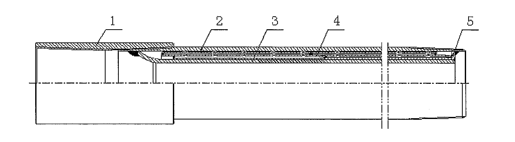
[0023]In order to make those skilled in the art better understand the technical solutions of the present invention, a further detailed description is made to a pre-stressed insulated tubing of the present invention in combination with drawings and particular embodiments.

[0024]As shown in FIG. 1, the pre-stressed insulated tubing of the present invention mainly includes an outer tube 2, an inner tube 3, a welding loop 5 and an insulated casing 4. The outer tube 2 is nested outside of the inner tube 3, a closed ring cavity is formed between the inner tube 3 and the outer tube 2, and the insulated casing 4 is arranged in the closed ring cavity.

[0025]Wherein, one end of the inner tube 3 is welded to inside of the outer tube 2 after being upset and flared, and after being pre-extended, the other end of the inner tube 3 is welded to the outer tube 2 via the adjusting welding loop 5.

[0026]In the present embodiment, the inner tube 3 and the outer tube 2 are both made of carbon steel. Wherei...


PUM


Abstract

The present invention relates to a pre-stressed insulated tubing, including an inner tube (3) and an outer tube (2) nested outside of the inner tube (3), and a closed ring cavity is formed between the inner tube (3) and the outer tube (2), wherein an insulated casing (4) is arranged in the closed ring cavity. The pre-stressed insulated tubing of the present invention features high vacuum degree, high thermal insulation level and long working life, and the insulated casing is reusable for cost saving.

Description

FIELD OF THE INVENTION[0001]The present invention belongs to a field of petroleum machinery technology, relates to a pre-stressed insulated tubing and particularly relates to a pre-stressed insulated tubing used in thermal recovery of heavy oil.BACKGROUND OF THE INVENTION[0002]In the prior art, a pre-stressed insulated tubing includes an inner tube, an outer tube and an insulating system formed between the inner tube and the outer tube. The following measures are usually used to form the insulating system: first, an outer wall of the inner tube and an inner wall of the outer tube are sandblasted so as to make surfaces of the tube walls smooth, thereby facilitating vacuum pumping; then, the outer wall of the inner tube is wound around with a plurality of layers (usually six layers) of thermal insulation materials or heat preservation materials such as glass wool cloth, aluminium silicate wool, aluminum foil, etc., getter is added into a cavity formed between the inner tube and the ou...

Claims


Application Information

Patent Timeline
IPC IPC(8): F16L9/18
CPCE21B17/00F16L9/045F16L59/065E21B36/003
Inventor PAN, YAOQINGWU, YONGNINGZHU, JINLIZHANG, XIAOHUIZHANG, WEIXU, ZHENYUJIA, ZHENYUCHEN, JIWANG, YI
Owner CNPC BOHAI EQUIP MFG
Features
  • Generate Ideas
  • Intellectual Property
  • Life Sciences
  • Materials
  • Tech Scout
  • Unparalleled Data Quality
  • Higher Quality Content
  • 60% Fewer Hallucinations
Learn More