Mass Spectrometer

a mass spectrometer and mass spectrometer technology, applied in the field of mass spectrometers, can solve the problems of deterioration of performance, linear ion traps with high upper limit of the amount of ions that can be stored, and saturation of output signals, so as to expand the dynamic range of measurement, the effect of multiplication factor restoration

Active Publication Date: 2012-07-12
SHIMADZU CORP
View PDF2 Cites 35 Cited by
  • Summary
  • Abstract
  • Description
  • Claims
  • Application Information

AI Technical Summary

Benefits of technology

[0035]In the mass spectrometer according to the first aspect of the present invention, an electric power is supplied from at least two independent power supplies to the multistage dynodes and the anode in the ion detector. Hence, the signals are less likely to be saturated. In addition, even in the case where the signal read out from the anode has undergone saturation or waveform distortion due to the incidence of an excessive amount of ions, the use of signals read out from the dynodes in which ions are under multiplication can prevent the influence of the signal saturation or waveform distortion from appearing on the mass spectrum. Even in the case where signal saturation or waveform distortion occurs as previously described, it is possible to promptly restore the decreased voltage in the dynode or anode in which the signal saturation or waveform distortion has occurred, so that the multiplication factor can be restored. Therefore, even when an excessive amount of ions are injected and then a very small amount of other ions are consequently injected, the secondary electrons corresponding to the very small amount of ions can be appropriately multiplied and can be read out as a detection signal. Hence, with the mass spectrometer according to the first aspect of the present invention, the dynamic range of the signal detection in the ion detector can be expanded more than ever before, which consequently expands the dynamic range of the measurement.
[0036]In addition, in the mass spectrometer according to the first aspect of the present invention, the output voltages of two or more independent power supplies can be appropriately adjusted so as to use a simple method for the arithmetic processing of a plurality of signals and thereby increase the processing speed. This alleviates a hardware load in processing signals, allowing a processing with inexpensive hardware.
[0037]In the mass spectrometer according to the second aspect of the present invention, even in the case where only one power supply is provided to apply voltages to the multistage dynodes and anode in the ion detector, a simple method for the arithmetic processing of a plurality of signals can be used to increase the processing speed. This alleviates a hardware load in processing signals, allowing a processing with inexpensive hardware.

Problems solved by technology

In addition, even when the amount of ions is lower than the upper limit, if the amount of ions stored in the ion trap is large, a deterioration of performance, such as the mass resolving power, disadvantageously occurs due to the effect of the interaction among the ions called a space-charge effect.
On the other hand, a linear ion trap has a high upper limit of the amount of ions that can be stored compared to three-dimensional quadrupole ion traps.
This disadvantageously results in saturation of an output signal which is read out from the anode provided in the final stage (which is sometimes called a collector).
However, even with such conventional methods as just described, it is difficult to sufficiently improve the dynamic range.
In such a case, even if a power is supplied independently to each of the dynodes as in the boosting method, the power feeding amount may transiently run short or a space-charge effect may occur by the electrons inside the secondary electron multiplier, which may lead to a temporary decrease in gain or a rounding of the output waveform.
Consequently, the noise level due to the thermal noise is not negligible, which becomes a restriction factor of the dynamic range.
However, even if there is no longer an excessive input, it is not possible to ensure a sufficient gain for a low-level input immediately after an excessive input, since the secondary electron multiplier requires a certain amount of time to recover from a decrease in gain and a rounding of waveform at each of the dynodes in the posterior portion and the anode.
This constitutes a factor of restricting the dynamic range and deteriorating the quantitative capability.
Accordingly, due to the arithmetic computation, the cost of the signal processing unit may be increased.
Further, the processing speed may be restricted due to the large amount of computation.

Method used


Image

  • Mass Spectrometer
  • Mass Spectrometer
  • Mass Spectrometer

Examples


first embodiment

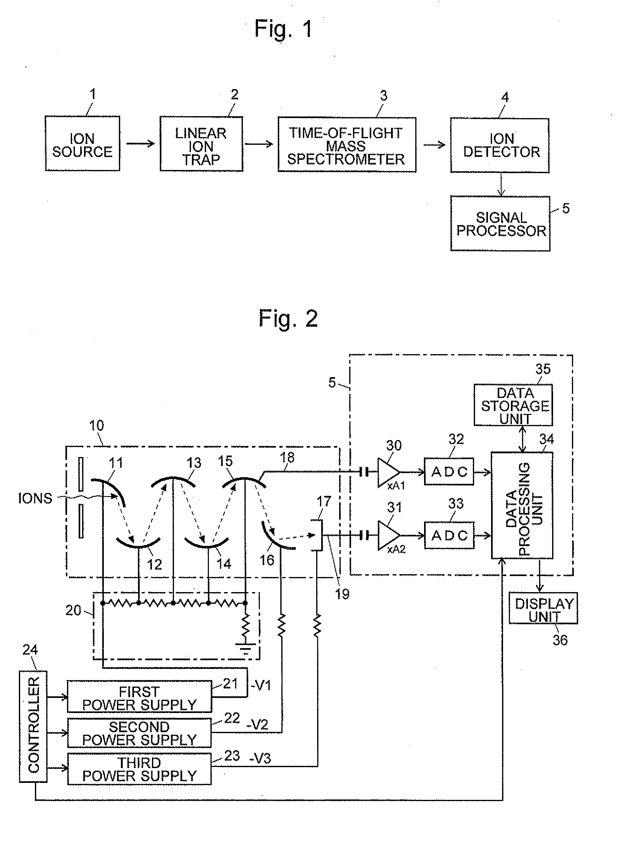
[0041]The first embodiment of the mass spectrometer according to the present invention will be described with reference to the attached figures. FIG. 1is a schematic configuration diagram of the mass spectrometer of the first embodiment.

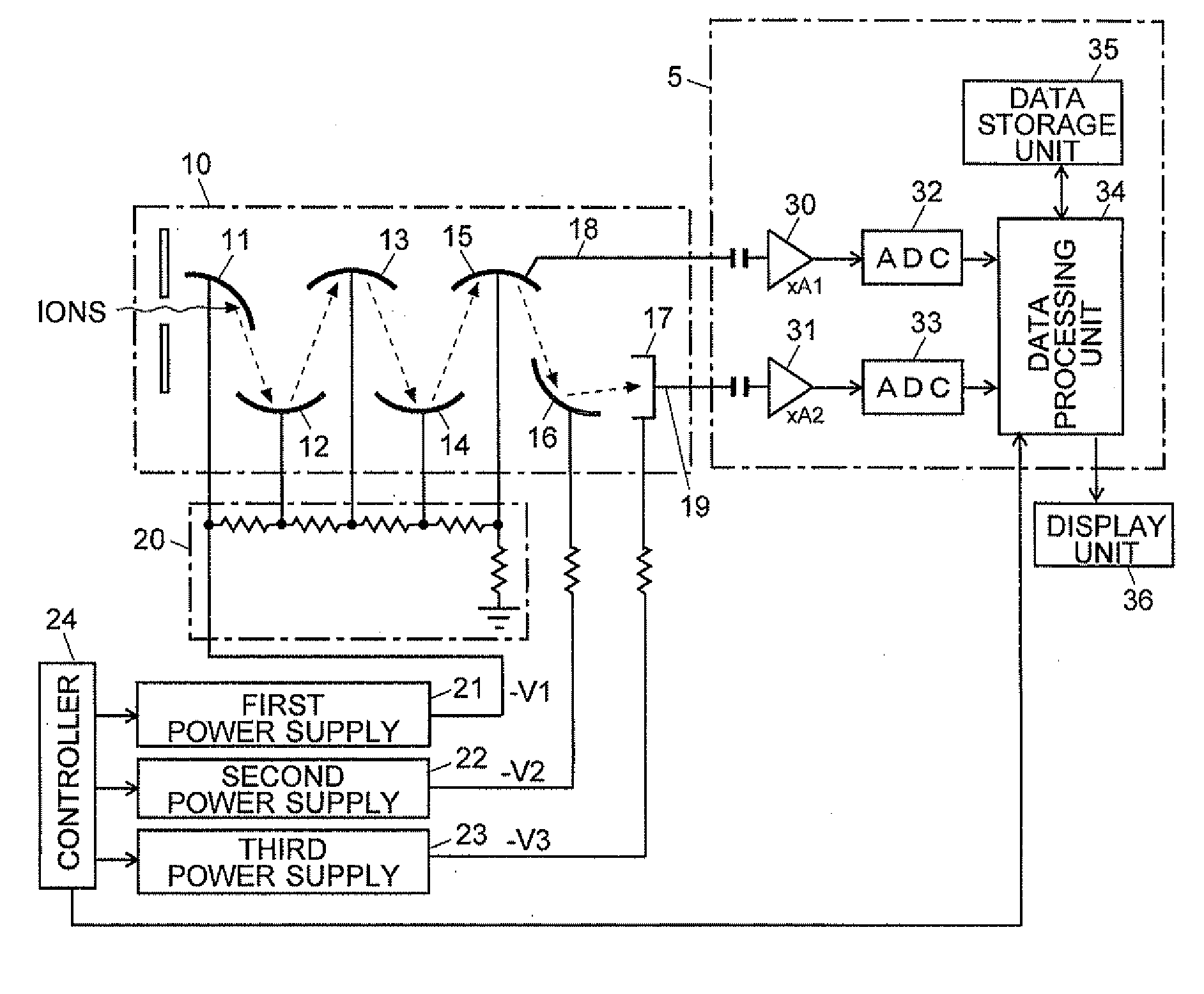
[0042]As shown in FIG. 1, the mass spectrometer of the first embodiment includes: an ion source 1 for ionizing sample molecules; a linear ion trap 2 for temporarily storing ions generated in the ion source 1; a time-of-flight mass spectrometer 3 for temporally separating a variety of ions in accordance with their mass-to-charge ratio m / z which are almost collectively ejected from the linear ion trap 2 at a predetermined timing; and an ion detector 4 for sequentially detecting ions arriving at the detector in a temporally separated form. These components are placed in a container (not shown) which is maintained at a vacuum atmosphere.

[0043]The signal detected by the ion detector 4 is sent to the signal processing unit 5, where a predetermined signal p...

modification example 2

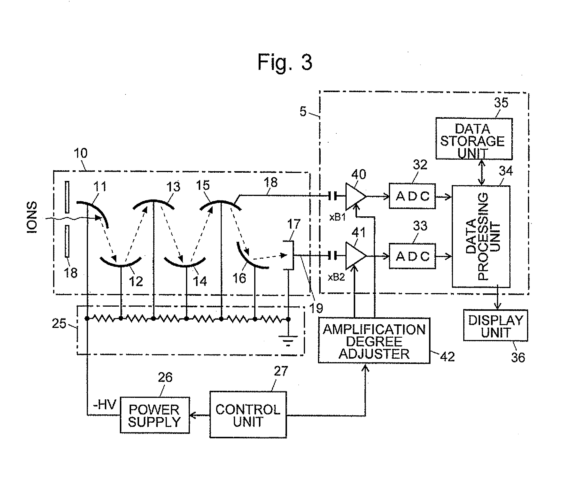
[0061]When a sample is measured to obtain mass spectrum data, one of the two detection data D1 and D2 obtained for the same point in time are selected as in the aforementioned manner, and only the selected data are stored in the data storage unit 35. Information (e.g., a one-bit flag) for indicating which of the detection data D1 and D2 have been selected is added, and if a mass spectrum is created and displayed offline, the added information is used to determine whether to perform a level correction, then a level correction is performed if necessary. The advantage of this method is that the required amount of data stored in the data storage unit 35 is merely about one half of the amount in the aforementioned method.

modification example 3

[0062]When a sample is measured to obtain mass spectrum data, one of the two detection data D1 and D2 obtained for the same point in time are selected as in the aforementioned manner. When the detection data D1 are selected, they are level-corrected and then stored in the data storage unit 35. In this case, only one piece of data is memorized for one point in time. Hence, in creating and displaying a mass spectrum offline, a time-of-flight spectrum can be easily created by reading out the detection data from the data storage unit 35.


PUM


Abstract

In an ion detector, power supplies (21 through 23) generating independently controllable voltages are provided to respectively apply voltages to first to fifth dynodes (11 through 15), a final dynode (16), and an anode (17) in a secondary electron multiplier (10). Furthermore, the signal from the anode (17) is extracted, and the signal from the fifth dynode (15), which has a low electron multiplication rate, is extracted. These two signals are concurrently converted into digital values, taken in by a data processing unit (34), and stored in a data storage unit (35). When a mass spectrum is created in the data processing unit (34), the two detected data for the same time are read out and the presence or absence of signal saturation or waveform deformation is determined from the values of one of the detection data. If there is a high probability of signal saturation, the detection data based on the signals in the intermediate stages are selected, and the level of the selected data is corrected. The application of independent voltages to the secondary electron multiplier (10) makes the signal saturation less likely to occur. Even if saturation temporarily occurs, an unsaturated signal can be reflected in the mass spectrum.

Description

TECHNICAL FIELD[0001]The present invention relates to a mass spectrometer. In particular, it relates to a mass spectrometer in which an electron multiplier detector is used as an ion detector.BACKGROUND ART[0002]In a mass spectrometer, ions separated in accordance with their mass-to-charge ratio m / z in a mass separator are detected in an ion detector. In general, in an ion detector, a signal proportional to the number of received ions is read out. In particular, in a quantitative analysis, it is important that the range of the amount of detectable ions, i.e. the dynamic range, is wide. Main restriction factors of the dynamic range are the upper limit of the amount of ions to be mass analyzed and the upper and lower limits of the amount of ions that the ion detector itself can detect.[0003]For example, consider an ion trap time-of-flight mass spectrometer (IT-TOFMS) in which a three-dimensional quadrupole ion trap and a time-of-flight mass spectrometer are combined. A three-dimension...

Claims


Application Information

Patent Timeline
Patent Type & Authority Applications(United States)
IPC IPC(8): H01J49/26
CPCH01J49/025H01J43/30H01J43/18H01J43/025
Inventor IZUMI, HIDEAKI
Owner SHIMADZU CORP
Why Eureka
Try Eureka