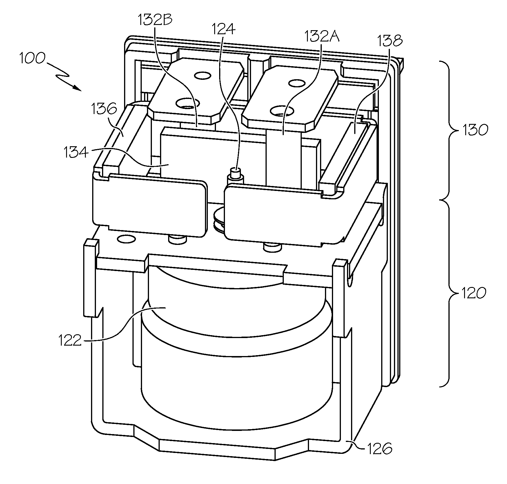
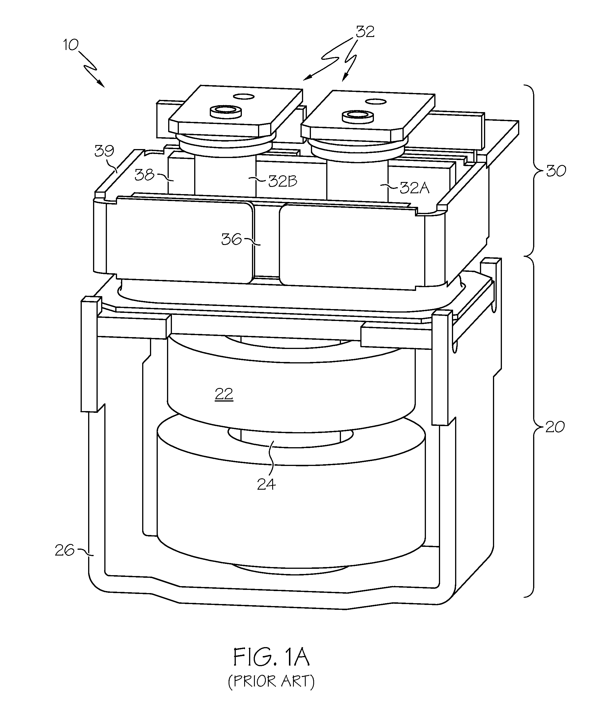
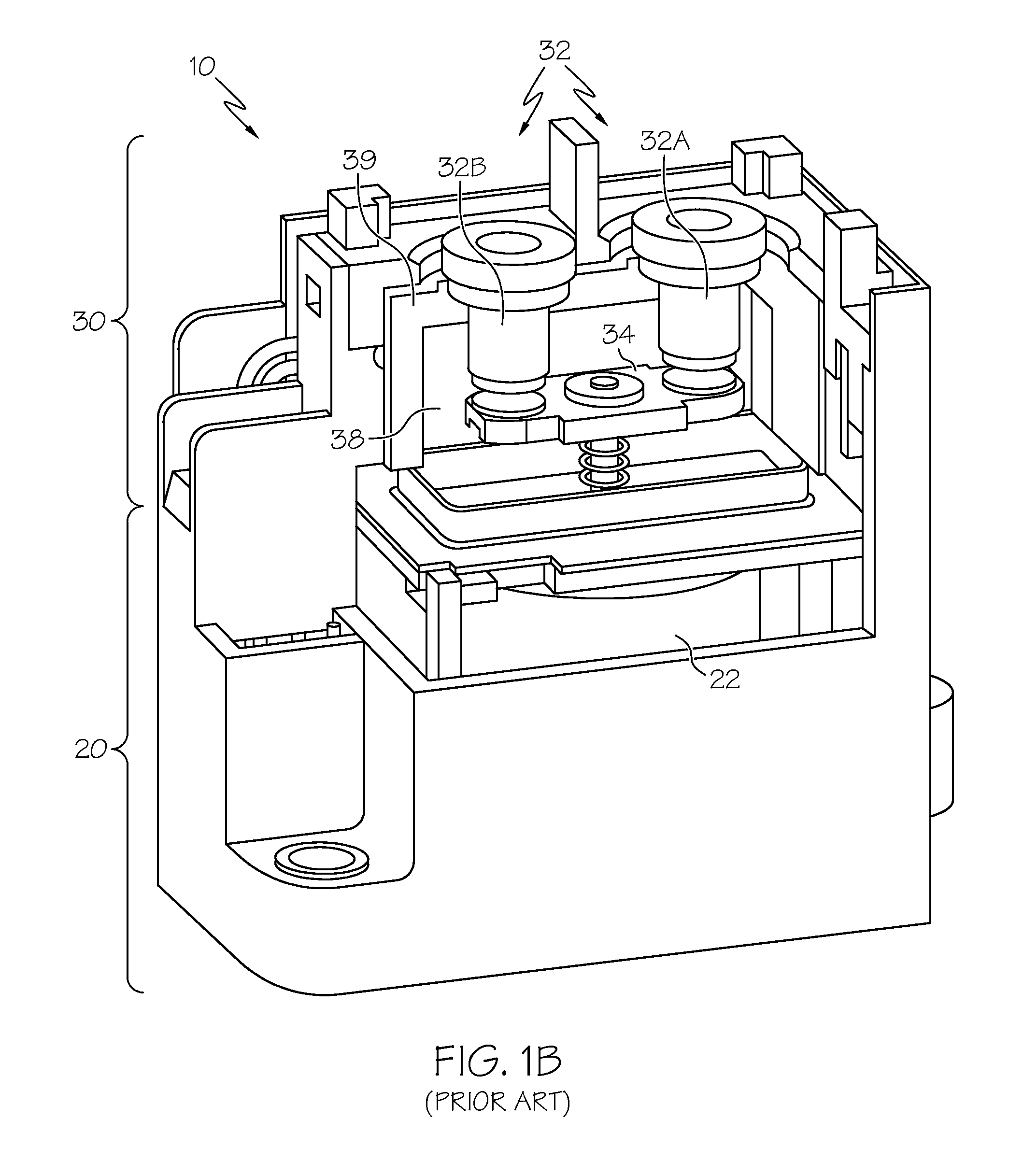
[0008]According to a first aspect of the invention, a switching
assembly is disclosed. In the present context, a switching
assembly corresponds to an arrangement of components that together allow for
selective opening and closing of an electric circuit. As such,
electric current passing through the switching circuit can be used to switch on or off a secondary electric circuit. In one example, such a
secondary circuit could be a work-performing circuit configured to deliver
electric current from one or more batteries (such as a
lithium-
ion battery) to an
electric motor or other devices that can provide propulsive power for a car,
truck or related vehicular or motive application. In particular form, the switching
assembly of the present invention may be configured as a
relay, switch or related circuit-opening and circuit-closing mechanism. The supplemental magnets used for a relay, switch or related solenoid-based device can be arranged in conjunction with the direction of
electric current flow through the terminals and contact plate to reduce the magnitude of the Lorentz force produced by the interaction of the
magnetic field and electric current while simultaneously reducing the arcing associated with de-energized contacts. This latter feature, with its reduction in the likelihood of a partially-
open contact, promotes more stability in the current path from one terminal to the other. In other words, since the Lorentz force on the contact plate is minimized, the potential for the contact to be inadvertently disconnected from the terminals due to such force is decreased.
[0009]The rotary nature of the connection between the solenoid, contact plate and terminals ensures a faster disconnect; this in turn produces a faster
elimination of the arcing produced during contact plate and terminal disconnect. Furthermore, the rotary nature of the connection between the solenoid and the contact plate promotes stronger joint potentials and a concomitant increase in device robustness for high-
voltage contactors such as those encountered in
lithium-
ion battery systems. For example, unlike a linear solenoid (where the shaft interacts with the contact plate through a relatively small ball-shaped region, the rotary design may enable a large region of connection that promotes a more durable construction.
[0010]As stated above, one
advantage of the design is that it prevents the Lorentz force from inadvertently opening the contact between the plate and the terminals during
high current pulses. Such prevention is in evidence in situations where the supplemental (i.e., arc-extinguishing or arc-breaking) magnets are placed such that the current and magnetic field are in parallel as shown and described below. In theory, this
parallel arrangement of the current flow and the magnetic field equates to complete
elimination of the Lorentz force on the contact plate. Importantly, because this force on the contact plate has nothing to do with the arc-breaking effect of the Lorentz force on the area around the connection between the terminals and the contact plate, such arc-
breaking force still exists because the current at that location is orthogonal rather than parallel with the magnetic field.
[0011]The rotary design according to the present invention may have variations as well. In one variation, the supplemental magnets may, instead of being placed such that the field produced between them is parallel to the flow of electric current through the connected terminals, be placed across the terminals such that the magnetic field is directed in an orthogonal direction to that of the current flowing through the terminals. Under linearly-actuated contact plate configurations (i.e., where the
plunger from the solenoid translates under the force of an applied current through the solenoid's coil), such orthogonality between the magnetic field and the current flow through the terminals may promote the Lorentz force problems discussed above, as induced forces could lead to inadvertent opening of the contact between the plate and the terminals during normal operation. Under a variation of the present invention where such orthogonality does exist, a Lorentz force is generated, but nevertheless avoids the contact opening difficulties discussed above because the contact points are oriented in a direction not influenced by the induced force. Under this variation of the design, the supplemental
magnet configuration may be left in place in a manner generally similar to that of previous designs, but because of the nature of the rotary contact and the contact plate, the Lorentz force (while not eliminated in the same manner as the design discussed in the previous paragraphs) becomes less likely to interfere with the operation during
high current flows while maintaining the arc-extinguishing features of the supplemental magnets during contact opening and closing events.
[0013]Each of the above optional configurations has its own advantages. The first embodiment is effective in that by generally aligning the current and field, the generation of the Lorentz force is stunted. Thus, by aligning a magnetic field with a direction of current flow (or opposite of the current flow) in a contact plate disposed between magnets that are producing the field, the tendency of the Lorentz forces to interfere with the operation of a solenoid or other switch-activating mechanisms during normal (i.e., uninterrupted) current flow are precluded, while simultaneously preserving the Lorentz force used to promote arc extinguishing during a relay opening sequence (where the electric current travels in a direction normal to the field as well as the flow of current during routine closed-circuit operation). The second embodiment, even though oriented to leave the Lorentz force in place (by virtue of the generally orthogonal orientation of the current flow and the magnetic field), has more potential to be effectively packaged in a space-saving (i.e., square) configuration. As such, the configuration used will depend on the needs of the automotive or related
system into which the particular configuration is placed.


