Piezoelectric element, liquid ejecting head, and liquid ejecting apparatus

Inactive Publication Date: 2012-07-19
SEIKO EPSON CORP
View PDF5 Cites 2 Cited by
  • Summary
  • Abstract
  • Description
  • Claims
  • Application Information

AI Technical Summary

Benefits of technology

[0018]This structure can suppress leakage current and achieve a piezoelectric element that can exhibit a high insulation value. In a

Problems solved by technology

If leakage current is liable to occur, the material is likely to crack when it is used while a high voltage is applied, and is therefore difficult to use in a liquid ejecting head.
This issue arises not only in ink jet recording heads, but also in other liquid ejecting heads that eject droplets o

Method used


Image

  • Piezoelectric element, liquid ejecting head, and liquid ejecting apparatus
  • Piezoelectric element, liquid ejecting head, and liquid ejecting apparatus
  • Piezoelectric element, liquid ejecting head, and liquid ejecting apparatus

Examples


Embodiment Construction

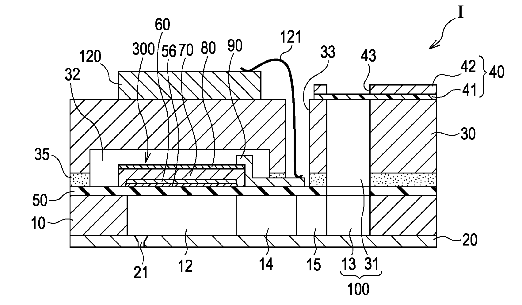
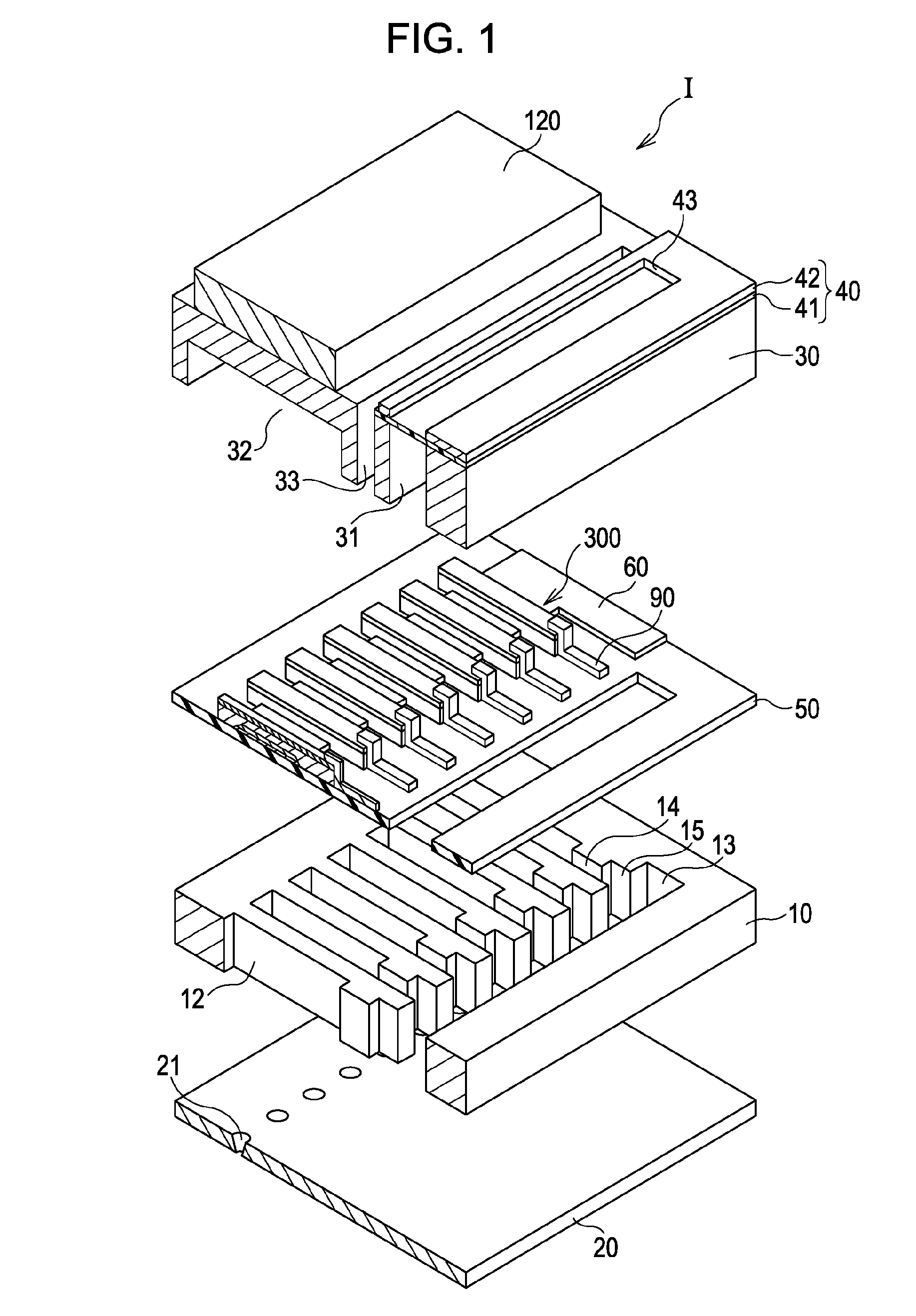
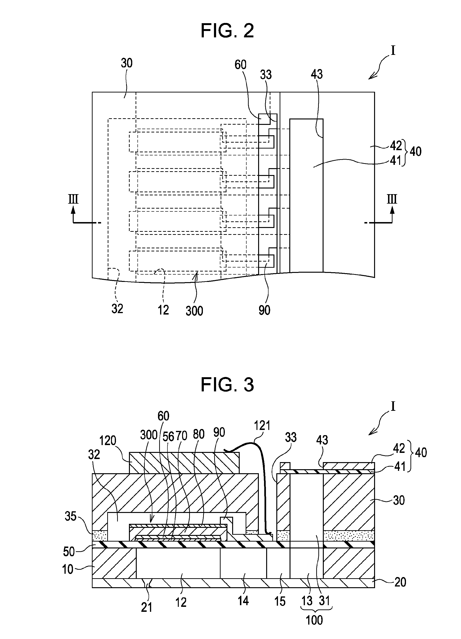
[0042]FIG. 1 is a schematic exploded perspective view of an ink jet recording head I, which is a type of liquid ejecting head, according to an embodiment of the invention. FIG. 2 is a plan view of the ink jet recording head I shown in FIG. 1. FIG. 3 is a sectional view taken along line III-III shown in FIG. 2. A flow channel substrate 10 is made of monocrystalline silicon, and a silicon dioxide elastic film 50 is disposed on one surface of the flow channel substrate 10, as shown in FIGS. 1 to 3.

[0043]The flow channel substrate 10 has a plurality of pressure generating chambers 12 arranged in parallel in the direction of their widths. The flow channel substrate 10 also has a communicating section 13 therein located outside the pressure generating chambers 12 in their longitudinal direction. The communicating section 13 communicates with the pressure generating chambers 12 through corresponding ink supply channels 14 and communication paths 15. The communicating section 13 communicate...


PUM


Abstract

A piezoelectric element comprises a piezoelectric layer consisting of a complex oxide having a perovskite structure containing bismuth and iron and electrodes provided to the piezoelectric layer. The complex oxide further contains a first dopant element that is at least one selected from the group consisting of sodium, potassium, calcium, strontium and barium, and a second dopant element that is cerium.

Description

CROSS-REFERENCE TO RELATED APPLICATIONS[0001]The entire disclosure of Japanese Patent Application No.2011-009282, filed Jan. 19, 2011 is expressly incorporated by reference.BACKGROUND[0002]1. Technical Field[0003]The present invention relates to a liquid ejecting head and a liquid ejecting apparatus, each including a pressure generating chamber communicating with a nozzle aperture and a piezoelectric element that includes a piezoelectric layer and electrodes applying a voltage to the piezoelectric layer and functions to change the pressure in the pressure generating chamber, and relates to the piezoelectric element.[0004]2. Related Art[0005]Some piezoelectric actuators used in liquid ejecting heads include a piezoelectric element having a structure in which a piezoelectric layer made of a piezoelectric material capable of electromechanical conversion, such as a crystallized dielectric material, is disposed between two electrodes. Ink jet recording heads are a typical type of liquid ...

Claims


Application Information

Patent Timeline
IPC IPC(8): B41J2/045H01L41/04B41J2/055B41J2/135B41J2/14B41J2/16C01G49/00H01L41/09H01L41/18H01L41/187H01L41/22H01L41/39
CPCB41J2/14233H01L41/332C04B35/2675C04B35/2683C04B35/2691C04B35/62218C04B2235/3201C04B2235/3206C04B2235/3213C04B2235/3215C04B2235/3229H01L41/0973H01L41/1878H01L41/318C04B35/26H10N30/2047H10N30/8561H10N30/078H10N30/082
Inventor MIYAZAWA, HIROMUYONEMURA, TAKAYUKIMOROZUMI, KOICHI
Owner SEIKO EPSON CORP
Why Eureka
Try Eureka