Method and apparatus for treating well flow-back and produced water or other wastewater

a technology of flow-back and produced water, applied in the field of water treatment, can solve the problems of insufficient suspension of larger flocs, achieve the effects of promoting crystal growth, enhancing precipitation, and promoting growth

Inactive Publication Date: 2012-08-09
TERVITA
View PDF7 Cites 24 Cited by
  • Summary
  • Abstract
  • Description
  • Claims
  • Application Information

AI Technical Summary

Benefits of technology

[0027]Rotation of the mixer provides gentle circulation within the clarifier silo, with axial inflow into the middle chamber from the upper and lower chambers, with radial flow from the upper and lower areas of the annular region into the upper and lower chambers, respectively, with radial outflow from the middle chamber into a middle area of the annular region, and with axial up-flow and down-flow from the middle area to the upper and lower areas, respectively, of the annular region. That is, the gentle mixing establishes separate upper and lower circulation patterns that promote crystal growth to a particular size. The circulation is sufficient to keep small crystals in suspension to promote growth but insufficient to keep larger flocs suspended. Once crystals grow to a certain size, they settle to the bottom of the clarifier for subsequent separation.
[0028]The clarifier silo may also include one or more vertical recirculation lines to recirculate some of the heavier flocculates at the bottom of the vessel into the mixer chamber. Gentle recirculation of flocs may enhance precipitation due to the seeding effect and flocculation due to increased floc collisions.

Problems solved by technology

The circulation is sufficient to keep small crystals in suspension to promote growth but insufficient to keep larger flocs suspended.

Method used


Image

  • Method and apparatus for treating well flow-back and produced water or other wastewater
  • Method and apparatus for treating well flow-back and produced water or other wastewater
  • Method and apparatus for treating well flow-back and produced water or other wastewater

Examples


first embodiment

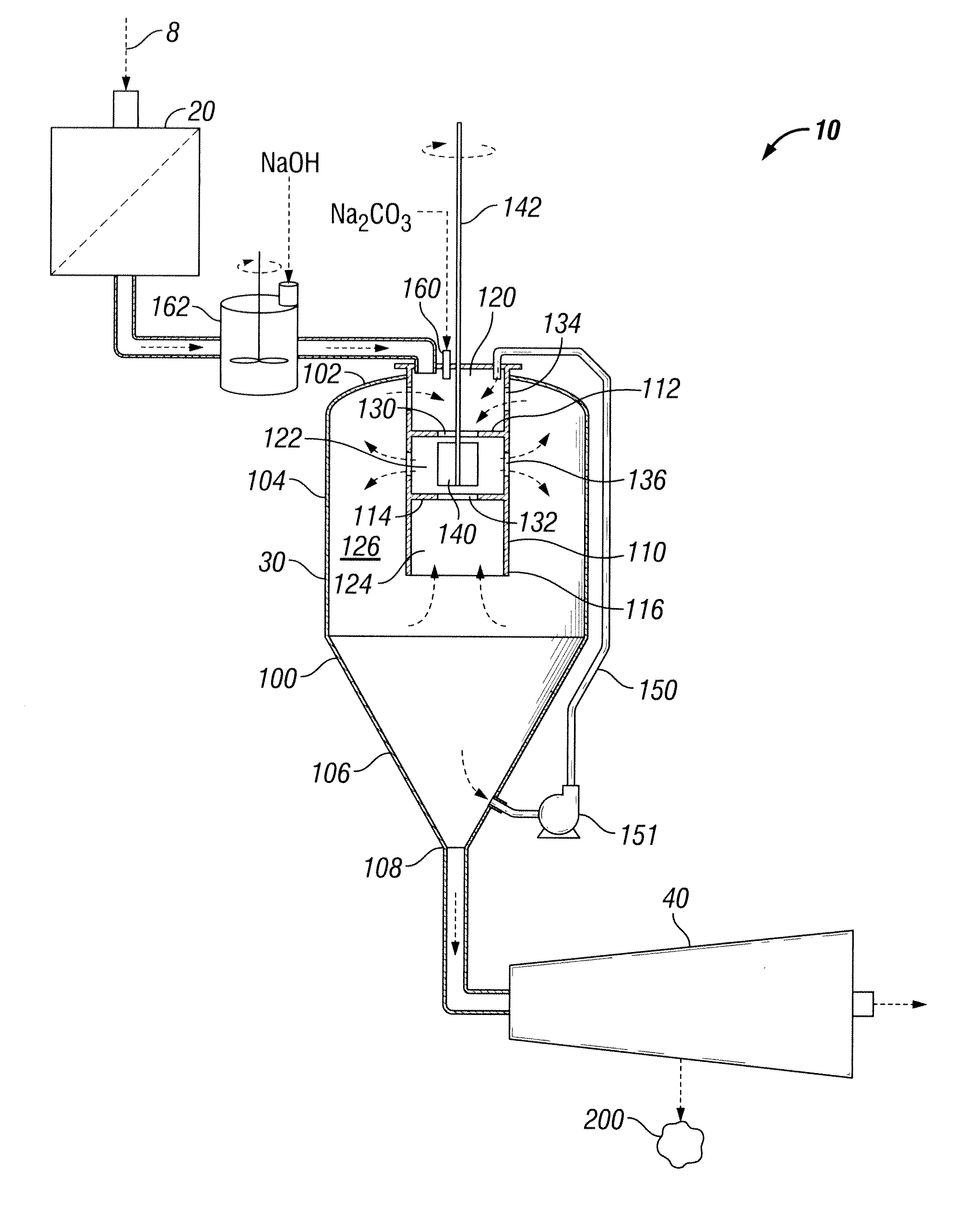
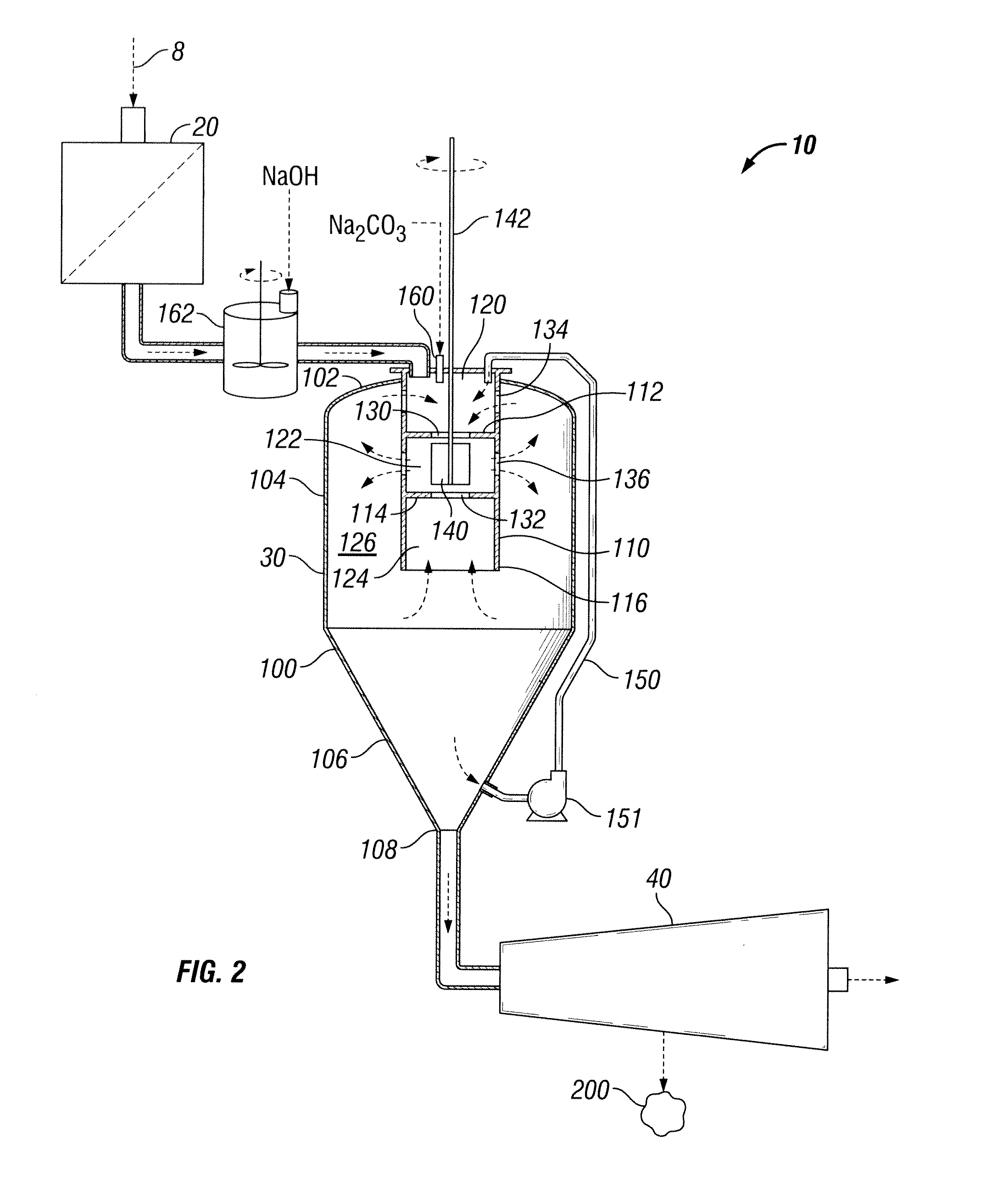
[0061]FIG. 6 illustrates clarifier silo 30 of FIG. 3, except that a portion of diffuser 110 is also cut away to reveal the arrangement of its various interior chambers according to a Diffuser 110 includes upper and lower transverse interior bulkheads 112, 114. Accordingly, diffuser 110 defines three interior chambers: An upper chamber 120 located above upper bulkhead 112; a middle chamber 122 located between upper and lower bulkheads 112, 114; and a lower chamber 124 located below lower bulkhead 114. An annular region 126 is defined outside of diffuser 110.

[0062]Upper bulkhead 112 has a central inlet port 130 formed therethrough that allows axial fluid flow into middle chamber 122 from upper chamber 120. Radial apertures 134 formed in the wall of diffuser 110 about upper chamber 120 allow fluid communication between annular region 126 and upper chamber 120. Similarly, lower bulkhead 114 includes a central inlet port 132 formed therethrough that allows axial fluid flow into middle c...

second embodiment

[0065]FIG. 8 illustrates clarifier silo 30 of FIG. 3, except that a portion of diffuser 110′ is also cut away to reveal the arrangement of its various interior chambers according to a FIG. 9 is a detailed perspective view of the diffuser 110′ and mixer 140′ of FIG. 8, shown with diffuser 110′ in axial cross section. Referring to both FIGS. 8 and 9, unlike diffuser 110 of FIGS. 6 and 7, diffuser 110′ does not includes transverse interior bulkheads. Rather the three interior chambers of diffuser 110′—upper chamber 120, middle chamber 122, and lower chamber 124—are demarked by mixer 140′. Mixer 140′ includes an upper propeller 141 and a lower propeller 143. Upper chamber 120 is located above upper propeller 141. Middle chamber 122 is located below upper propeller 141 and above lower propeller 143. Lower chamber 124 is located within diffuser 110′ below lower propeller 143.

[0066]Upper propeller 141 is pitched so that when rotated, fluid axially flows from upper chamber 120 into middle ...


PUM

PropertyMeasurementUnit
pHaaaaaaaaaa
circumferenceaaaaaaaaaa
areaaaaaaaaaaa

Abstract

A polymer-free method and self-draining self-cleaning apparatus for treatment of water with high total dissolved solids including optional pretreatment, precipitation/flocculation, and separation. The pH is raised by addition of caustic soda and/or soda ash. In a vertical clarifier silo, the feed is gently mixed to cause dissolved solids to precipitate and agglomerate to form suspended flocculates. The clarifier includes an internal mixer surrounded by a cylindrical tube diffuser. Rotation of the mixer provides gentle dual circulation patterns within the clarifier that allow for flocculates of a predetermined size to settle from suspension. The clarifier may also include one or more vertical recirculation lines to recirculate some of the heavier flocculates at the bottom of the vessel into the mixer chamber to enhance precipitation via the seeding effect. The suspended flocculates are stripped from the feed water in a centrifugal separator. The clarifier silo may be trailer mounted for rapid deployment.

Description

BACKGROUND OF THE INVENTION[0001]1. Field of the Invention[0002]This invention relates generally to the treatment of water, and in particular to treatment of water with high total dissolved solids, such as water used in conjunction with oilfield services. For example, the invention relates to treating oily flow-back or produced water from an oil and gas well prior to disposal or for reuse as injection or fracture flow-back water.[0003]2. Background Art[0004]Fracture flow-back water and water produced from a well may contain hydrocarbons, solids, bacteria, and heavy metals. Produced water is generated in the process of lifting oil and gas from subterranean formations that also include water. Water accompanies oil and gas as it is lifted to the surface. Reinjection of this produced water improves the recoverable reserves from a reservoir by establishing an external water drive and by maintaining reservoir pressure. Produced water may also be reused to fracture formations.[0005]Produce...

Claims


Application Information

Patent Timeline
Patent Type & Authority Applications(United States)
IPC IPC(8): C02F1/52C02F1/38C02F1/40
CPCC02F1/38C02F1/56C02F1/683C02F2101/20C02F2103/365B01F2005/0034B01D21/01B01D21/262B01D21/286B01F7/00633B01F7/168C02F2209/06B01F2025/918B01F27/191B01F27/861
Inventor BLY, JR., JOSEPH M.STACY, MELVIN O.PROANO, ENRIQUE M.
Owner TERVITA
Why Eureka
Try Eureka