

Carbon film
a technology of carbon film and mcd film, applied in the field of carbon film, can solve the problems of deteriorating the transmittance though the surface becomes planar, lack of surface planarity of mcd film, and inability to obtain sufficient transmittance, etc., to achieve high refraction index, small double refractivity, and high transparency
- Summary
- Abstract
- Description
- Claims
- Application Information
AI Technical Summary
Benefits of technology
Problems solved by technology
Method used
Image

Examples
example
[0079]The present invention is to be described more specifically. However, the invention is no, way restricted by such examples.
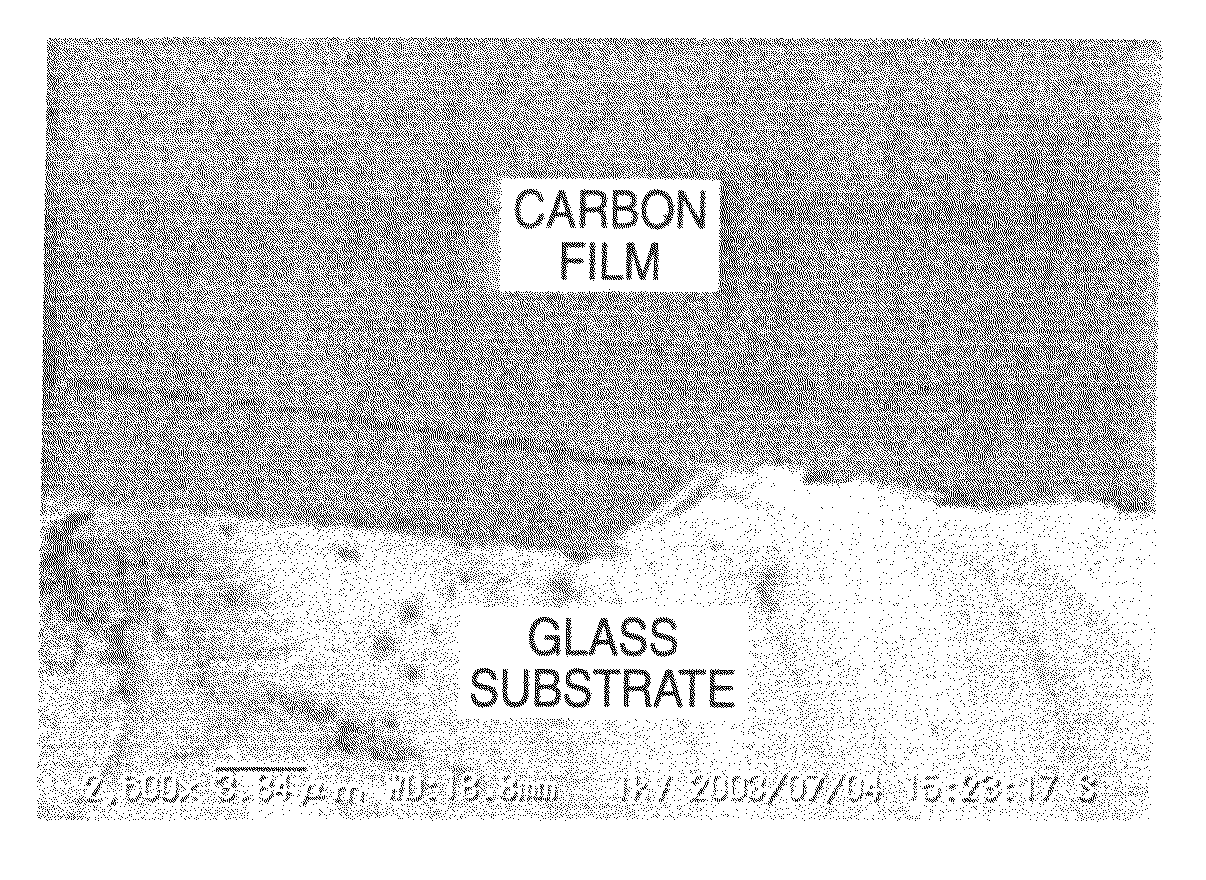
[0080]As a substrate, glass (borosilicate glass and soda lime glass) cut out to 300 mm×300 mm was used. Further, for manufacturing a specimen for evaluation, a wafer-like glass substrate of 4 inch diameter was also used. For increasing the density of nuclear formation of the carbon particles and forming a uniform film, a pre-treatment (deposition treatment of nano-crystal diamond particles) was conducted to the substrate before film formation.
[0081]A colloidal solution in which nano-crystal diamond particles of an average grain size of 5 nm were dispersed in pure water (manufactured by limited company, Nanocarbon Research Institute Ltd., products name: Nanoamand), a solution in which nano-crystal diamond particles of an average grain size of 30 nm or 40 nm were dispersed in pure water (manufactured by Tomei Diamond Co. Ltd., products name, MD30 and MD40 res...
PUM
| Property | Measurement | Unit |
|---|---|---|
| grain size | aaaaa | aaaaa |
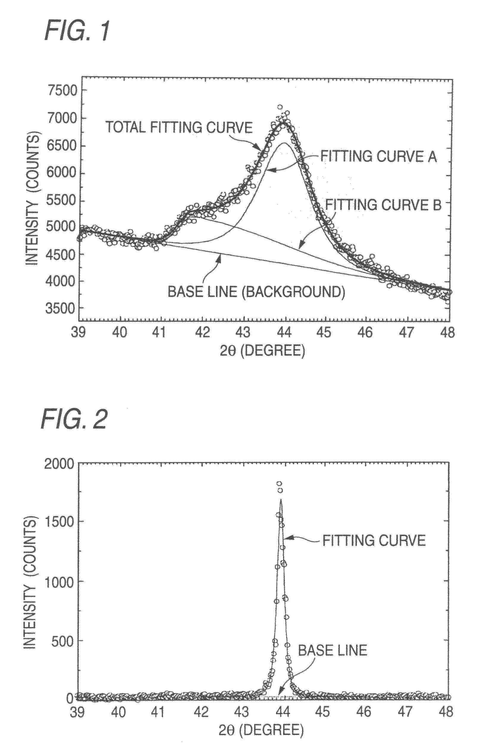
| Bragg's angle | aaaaa | aaaaa |
| Bragg's angle | aaaaa | aaaaa |
Abstract
Description
Claims
Application Information