Cement to make thermal shock resistant ceramic honeycomb structures and method to make them

a honeycomb structure and ceramic technology, applied in the field of ceramic filters, can solve the problems of reducing effectiveness, cracking of filters, and problems in cement use, and achieve the effects of improving dimensional tolerance, thermal shock resistance, and improving thermal shock resistan

Inactive Publication Date: 2012-08-16
DOW GLOBAL TECH LLC
View PDF4 Cites 11 Cited by
  • Summary
  • Abstract
  • Description
  • Claims
  • Application Information

AI Technical Summary

Benefits of technology

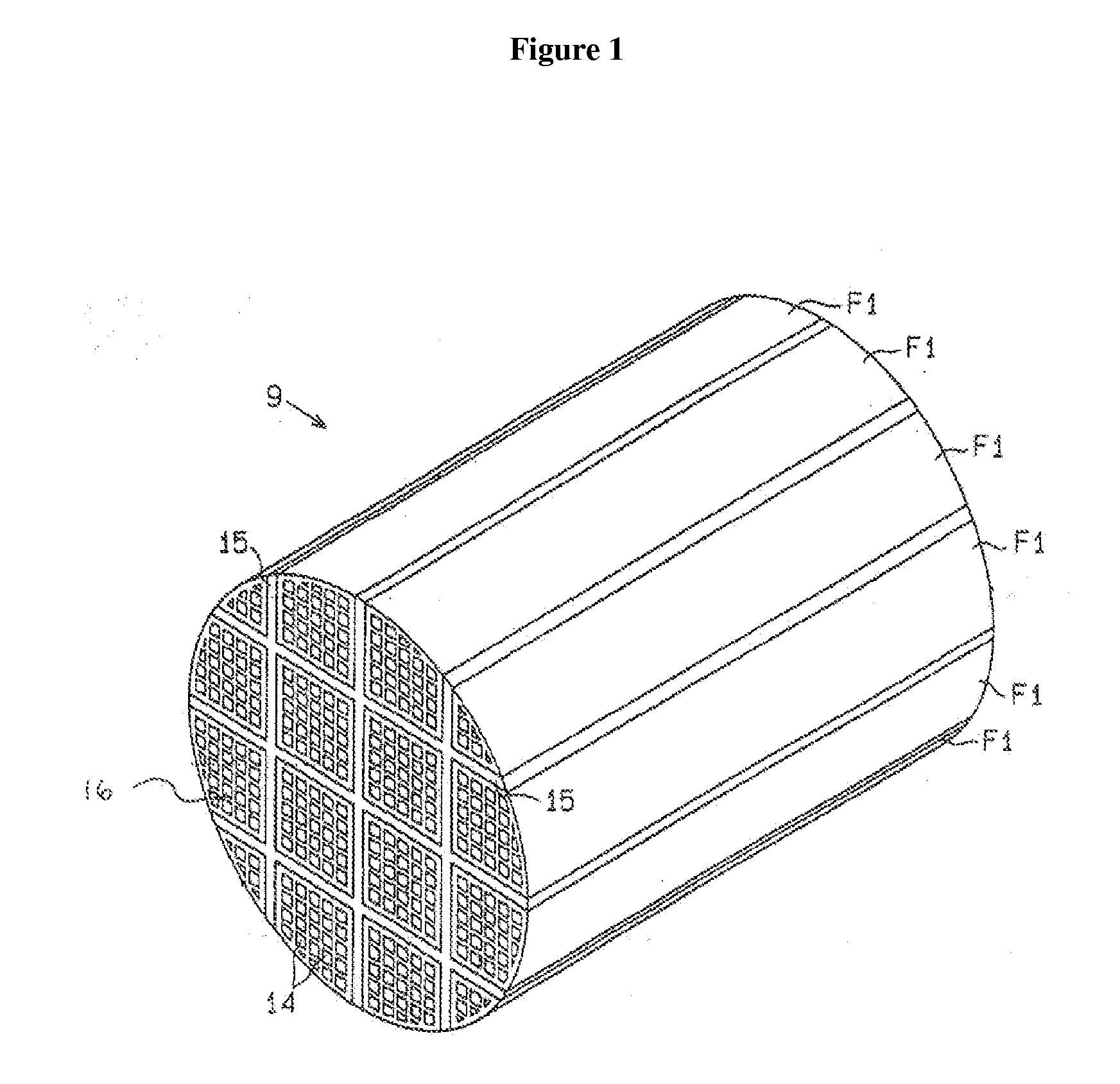
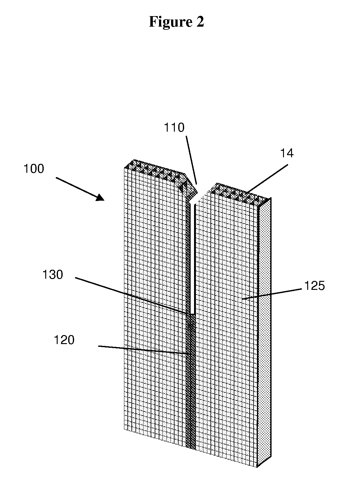
[0018]The ceramic honeycomb structures may be used in any applications requiring resistance to hot gases or liquids such as heat exchangers, catalyst supports and filters (e.g., molten metal and soot filters). The cement may be used to make porous ceramics requiring improved thermal shock resistance such as the aforementioned honeycomb structures. The cement may be used to coat the outer periphery (skin), precluding the open channel ends, of the honeycomb structures or honeycomb monoliths to improve the dimensional tolerance, thermal shock resistance or combination thereof.

Problems solved by technology

Diesel engines, because of the way they operate, emit soot particles or very fine droplets of condensate or a conglomerate of the two (particulates) as well as typical harmful gasoline engine exhausts (i.e., HC and CO).
This burning of soot results in stresses from axial and radial temperature differences that can cause cracking of the filter.
Unfortunately, the use of these augmenting materials results in problems in using the cement or reduced effectiveness.
For example, the use of organic binder helps in reducing separation of particles in the cement, but then must be removed slowing the process to make the part and also risking damage due to thermal gradients due to combustion of the organics and pressure from evolving gases.
The use of fibers also tends to lower the thermal mass and thermal conductivity of the cement layer due to inefficient packing and inability to load the fibers to any great extent into a carrier fluid without excessive viscosity increases.

Method used


Image

  • Cement to make thermal shock resistant ceramic honeycomb structures and method to make them
  • Cement to make thermal shock resistant ceramic honeycomb structures and method to make them
  • Cement to make thermal shock resistant ceramic honeycomb structures and method to make them

Examples


example 1

[0071]Cement was prepared by mixing 30.0% by weight of 300 micrometer agglomerates of a mullite precursor, (Component A), 14.74% by weight of graphite available from Cumming Moore Carbon Inc., Detroit, Mich. under the tradename A625 having a average particle size of about 30 micrometers (Component B), 7.89% by weight attrited alumina and clay (Component C), 1.05% by weight of a cellulose ether binder METHOCEL A4M (available from The Dow Chemical Company, Midland Mich.) (Component D) and 46.32% of water.

[0072]The attrited mixture of Component C was made using 53% by weight of Todd Dark ball clay (from Kentucky Tennessee Clay Company), 44% by weight of kappa alumina from Selecto Inc. Suwanee, GA and 3% talc MB-50-60 from Whitaker-Clark-Daniel Inc. The powders were milled for 3 hours using laboratory attritor (available from Union Process Inc. Akron, Ohio) at 500rpm using 5 mm yttrium Stabilized Zirconia balls in a 500 ml container. The attrited powder had an average particle size betw...


PUM

PropertyMeasurementUnit
porosityaaaaaaaaaa
porosityaaaaaaaaaa
porosityaaaaaaaaaa

Abstract

An improved ceramic honeycomb structure is comprised of at least two separate smaller ceramic honeycombs that have been adhered together by a cement layer comprised of a cement layer has at least two regions of differing porosity or cement layer where the ratio of toughness / Young's modulus is at least about 0.1 MPa·m1 / 2 / GPa.

Description

CLAIM OF BENEFIT OF FILING DATE[0001]The present application claims the benefit of the filing date of U.S. Application Ser. No. 61 / 2760,043, filed Nov. 11, 2009, which is hereby incorporated by reference for all purposes.FIELD OF THE INVENTION[0002]The present invention relates to a ceramic filter having improved thermal shock resistance and method to make them. In particular, the filter and method relate to the use of an improved ceramic cement for assembling ceramic particulate filters together to make a larger thermal shock resistant filter.BACKGROUND OF THE INVENTION[0003]Diesel engines, because of the way they operate, emit soot particles or very fine droplets of condensate or a conglomerate of the two (particulates) as well as typical harmful gasoline engine exhausts (i.e., HC and CO). These “particulates” (herein Diesel soot), are rich in condensed, polynuclear hydrocarbons, some of which may be carcinogenic.[0004]As the awareness of the danger Diesel soot presents to health ...

Claims


Application Information

Patent Timeline
Patent Type & Authority Applications(United States)
IPC IPC(8): B32B3/12B32B37/18C04B12/00
CPCB01D46/2425Y10T428/24149B01D46/2448B01D46/2459B01D2046/2433B01D2046/2437B01D2046/2496C04B26/285C04B35/185C04B37/005C04B38/0006C04B38/0019C04B2111/00793C04B2111/2084C04B2111/343C04B2235/3217C04B2235/322C04B2235/3463C04B2235/349C04B2235/3826C04B2235/425C04B2235/5436C04B2235/96C04B2237/062C04B2237/341C04B2237/597C04B2237/708F01N2330/06F01N2330/30F01N2450/28B01D46/2444C04B14/024C04B14/041C04B14/10C04B14/303C04B14/324C04B38/0054C04B38/0074C04B38/068B01D46/24492B01D46/24491B01D46/2498B01D46/24494B01D46/2478B01D46/24495B01D39/20B01D46/2429C04B37/003
Inventor PYZIK, ALEKSANDER J.SHINKEL, NICHOLAS M.PRUNIER, JR., ARTHUR R.GOSS, JANET M.YANG, KWANHO
Owner DOW GLOBAL TECH LLC
Why Eureka
Try Eureka