Eureka AIR delivers breakthrough ideas for toughest innovation challenges, trusted by R&D personnel around the world.

Methods for controlling melt temperature in a czochralski grower

a technology of czochralski grower and melt temperature, which is applied in the direction of polycrystalline material growth, crystal growth process, polycrystalline material growth, etc., can solve the problems of reducing heater power, further time loss, and process taking non-productive time, so as to improve the temperature of the melt more efficiently, controllable reduce the melt temperature, and improve the effect of insulation

Inactive Publication Date: 2012-08-23
SOLAICX
View PDF2 Cites 10 Cited by
  • Summary
  • Abstract
  • Description
  • Claims
  • Application Information

AI Technical Summary

Benefits of technology

[0009]A further aspect of the invention is that it provides a means for increasing the temperature in the melt more efficiently by using heater power. This can be more effective than temperature control in conventional CZ growers, because the melt region can be better insulated than would be practical in a conventional grower. In a conventional CZ grower, too much insulation makes it difficult to remove heat from the melt by radiation or conduction when the process requires it. Because an aspect of the invention provides a different means for controllably reducing melt temperature, better insulation can be provided around the heaters. This reduces the heater power required and makes the melt temperature increase more rapidly as heater power is increased. This also makes it possible to achieve the same melt temperatures while operating the heaters at lower temperatures. Lower operating temperatures extend the useful heater lifetime and reduce significantly the production of gases at the heaters that can contaminate the silicon melt, and critically degrade the quality of the silicon ingots.
[0010]The foregoing aspects of the invention provide the advantages of reducing the electric power required to operate a CZ grower, while increasing the speed with which the melt temperature can be raised or lowered in a controlled manner. Also, the lifetime of heater components is extended and production of contaminating gases from the heater elements can be greatly reduced, resulting in higher quality ingots.

Problems solved by technology

This process takes non-productive time during which solid poly-crystalline feedstock is added to the crucible and crystals are not being produced.
When the addition of material is completed, heater power is reduced and further time is lost waiting for the melt thermal conditions to stabilize at the correct conditions for pulling a monocrystalline ingot.
Reducing the melt temperature is accomplished by reducing the heater power, but this can take a long time, particularly in a well-insulated CZ grower, because the heat must exit the grower for the temperature to drop.
Reducing the grower insulation allows the melt temperature to be reduced more quickly, but causes the grower to consume more energy and requires the heaters to be at higher temperature during parts of the growth cycle.
Operating heaters at a higher temperature shortens their life and increases the production of gases, such as carbon monoxide, that can become dissolved in the molten silicon, contaminating and reducing the quality of the ingots produced.
Therefore, what is needed is a temperature control system that provides the capability of efficiently increasing or decreasing the melt temperature while saving energy and reducing the need for operating heaters at high temperatures, which shortens their useful life and produces gases that can contaminate the molten silicon in the grower.
In all CZ processes, reducing the melt temperature too slowly can result in loss of structure in the growing crystal.
Thus, a heavily insulated conventional CZ system is difficult to control.
On the other hand, reducing temperature too quickly by extracting energy rapidly can lead to loss of structure in a growing ingot due to thermal shock.
In a conventional CZ grower, too much insulation makes it difficult to remove heat from the melt by radiation or conduction when the process requires it.
This reduces the heater power required and makes the melt temperature increase more rapidly as heater power is increased.
Lower operating temperatures extend the useful heater lifetime and reduce significantly the production of gases at the heaters that can contaminate the silicon melt, and critically degrade the quality of the silicon ingots.

Method used


Image

  • Methods for controlling melt temperature in a czochralski grower
  • Methods for controlling melt temperature in a czochralski grower
  • Methods for controlling melt temperature in a czochralski grower

Examples


Embodiment Construction

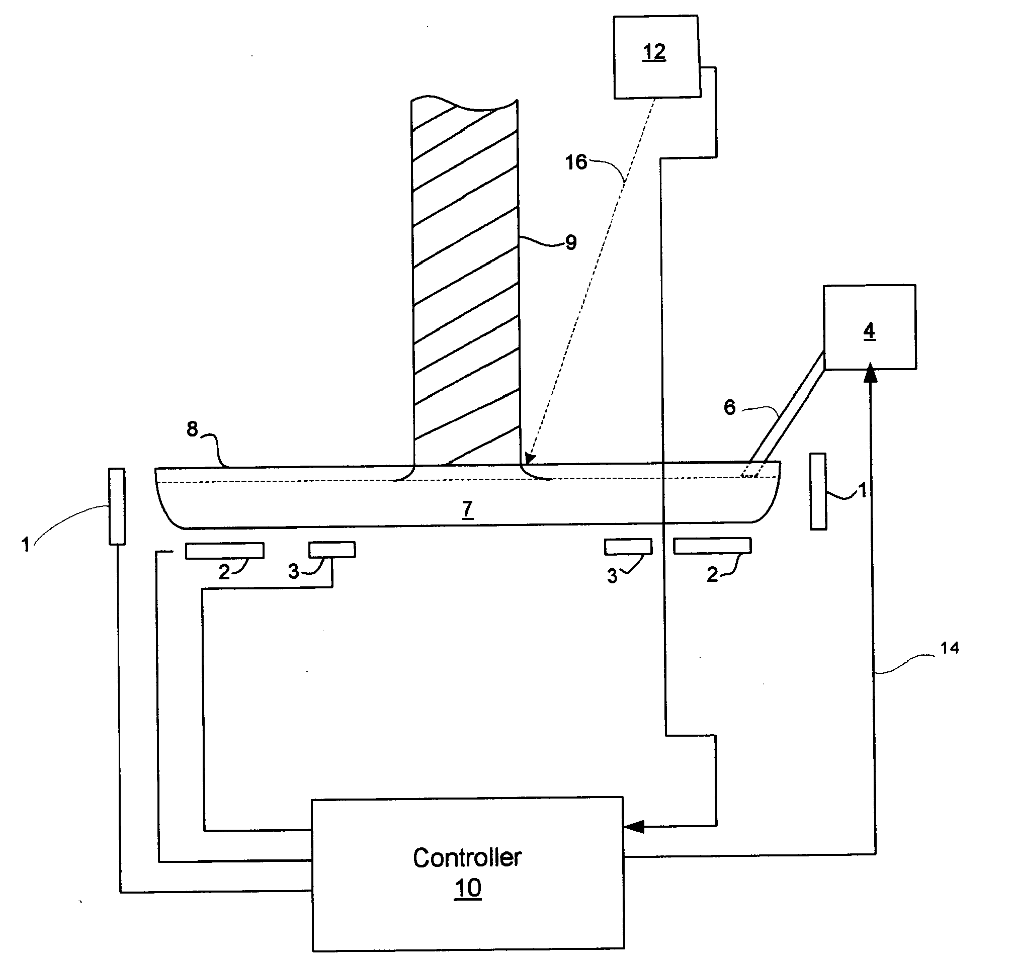
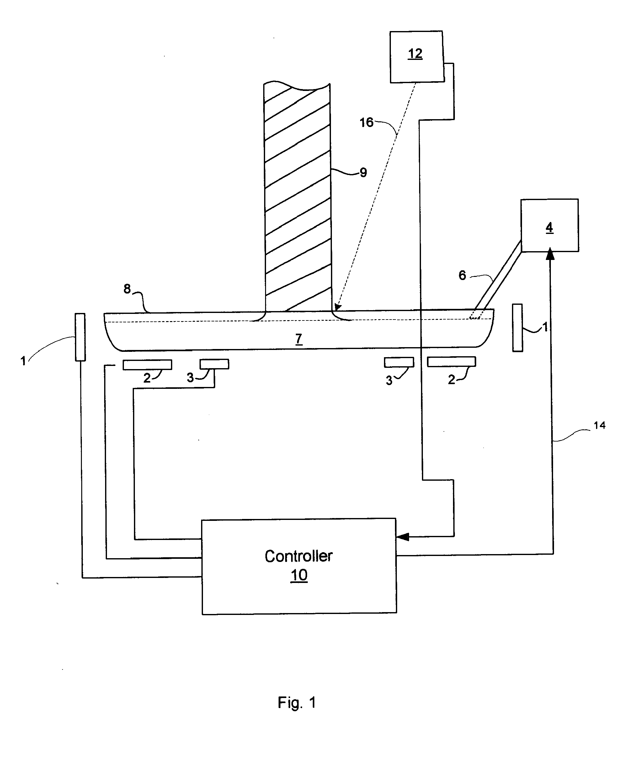
[0014]Referring to FIG. 1, a crystal growing system according to an aspect of the present invention provides a crucible 8 containing melt 7 from which an ingot 9 is being pulled. During the crystal pulling process, it is desirable to modify characteristics of the crystal being pulled, such as the rate of crystal solidification or the crystal diameter. One of the preferred means of doing this is by altering the melt temperature.

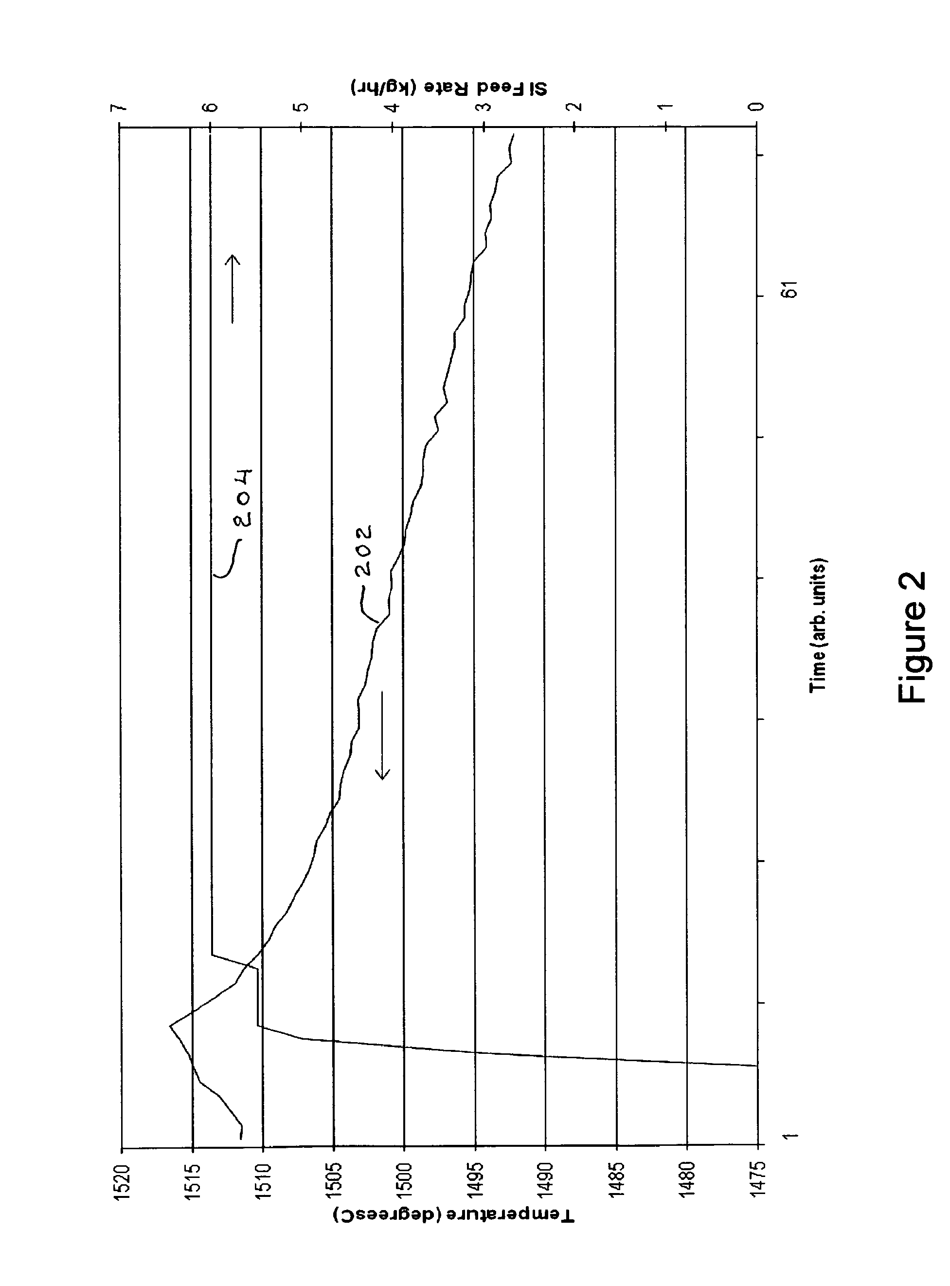
[0015]According to an aspect of the present invention, solid feedstock 5 may be added from feeder 4 through tube 6. This added solid feedstock material is at a much lower temperature than the surrounding melt and absorbs heat from the melt as the solid feedstock material's temperature rises, and as the solid material itself melts. As the solid feedstock material absorbs energy from the melt, the temperature of the melt falls immediately. This has been found to provide a very efficient, highly controllable means for cooling the melt and maintaining a desired me...


PUM


Abstract

In a Czochralski process for growing single crystal silicon ingots, a system is provided for adding solid material to the liquid silicon during crystal growth for the purpose of directly controlling the latent heat of fusion with respect to a crystal melt interface. In contrast to the standard method for controlling power to the crucible heater, the present system has been found to be much more effective for controlling melt temperature in the crucible, especially in heavily insulated systems. The system provides the advantage of reducing the electric power required to operate a Czochralski grower, while increasing the speed with which the melt temperature can be raised or lowered in a controlled manner.

Description

CROSS-REFERENCE TO RELATED APPLICATIONS[0001]This application is a Divisional of U.S. patent application Ser. No. 12 / 315,681, filed Dec. 4, 2008, which claims the benefit of U.S. Provisional Application No. 61 / 005,384, filed Dec. 4, 2007, both of which are incorporated herein by reference.FIELD OF THE INVENTION[0002]The field of the invention generally relates to growing single crystal silicon by the Czochralski (CZ) technique. In particular, the field of the invention relates to a system and method for controlling the characteristics of the liquid silicon from which a crystal is being pulled, resulting in improved mono-crystalline ingot yields.BACKGROUND OF RELATED ART[0003]In a conventional batch CZ process using solid recharge, a monocrystalline ingot is drawn from the melted silicon contained in a crucible. After an ingot has been pulled, the melted silicon in the crucible is replenished by adding solid feedstock to the crucible and melting it. When the crucible melt level has b...

Claims


Application Information

Patent Timeline
IPC IPC(8): C30B15/20C30B15/14C30B15/02
CPCC30B15/02C30B15/14Y10T117/1008C30B29/06C30B15/20
Inventor BENDER, DAVID L.JANIK, GARYSMITH, DAVID E.A.
Owner SOLAICX
Why Eureka
Eureka Blog
Learn More