Tube-shaped sputtering target

a sputtering target and tube-shaped technology, applied in the direction of transportation and packaging, vacuum evaporation coating, coating, etc., to achieve the effect of improving the known sputtering targ

Active Publication Date: 2012-08-23
MATERION ADVANCED MATERIALS GERMANY GMBH
View PDF3 Cites 20 Cited by
  • Summary
  • Abstract
  • Description
  • Claims
  • Application Information

AI Technical Summary

Benefits of technology

[0004]It is an object of the invention to improve the known sputtering targets, in order to attain even sputtering rates and evenly thick layers.

Problems solved by technology

Owing to the metal needing to be very pure (99.99 to 99.999%) for the CIGS application, the sputtering targets have a very coarse structure, which may then lead to the problems mentioned above.

Method used


Image

  • Tube-shaped sputtering target
  • Tube-shaped sputtering target
  • Tube-shaped sputtering target

Examples


Embodiment Construction

[0031]The invention is described below based on methods for preparing tubular targets according to the present invention and according to the prior art.

1. Method for producing a tubular target according to the invention:

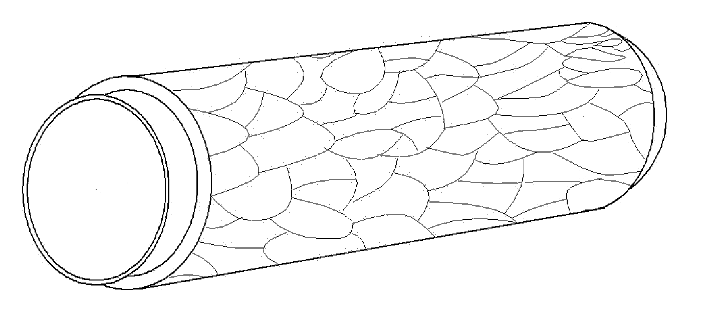
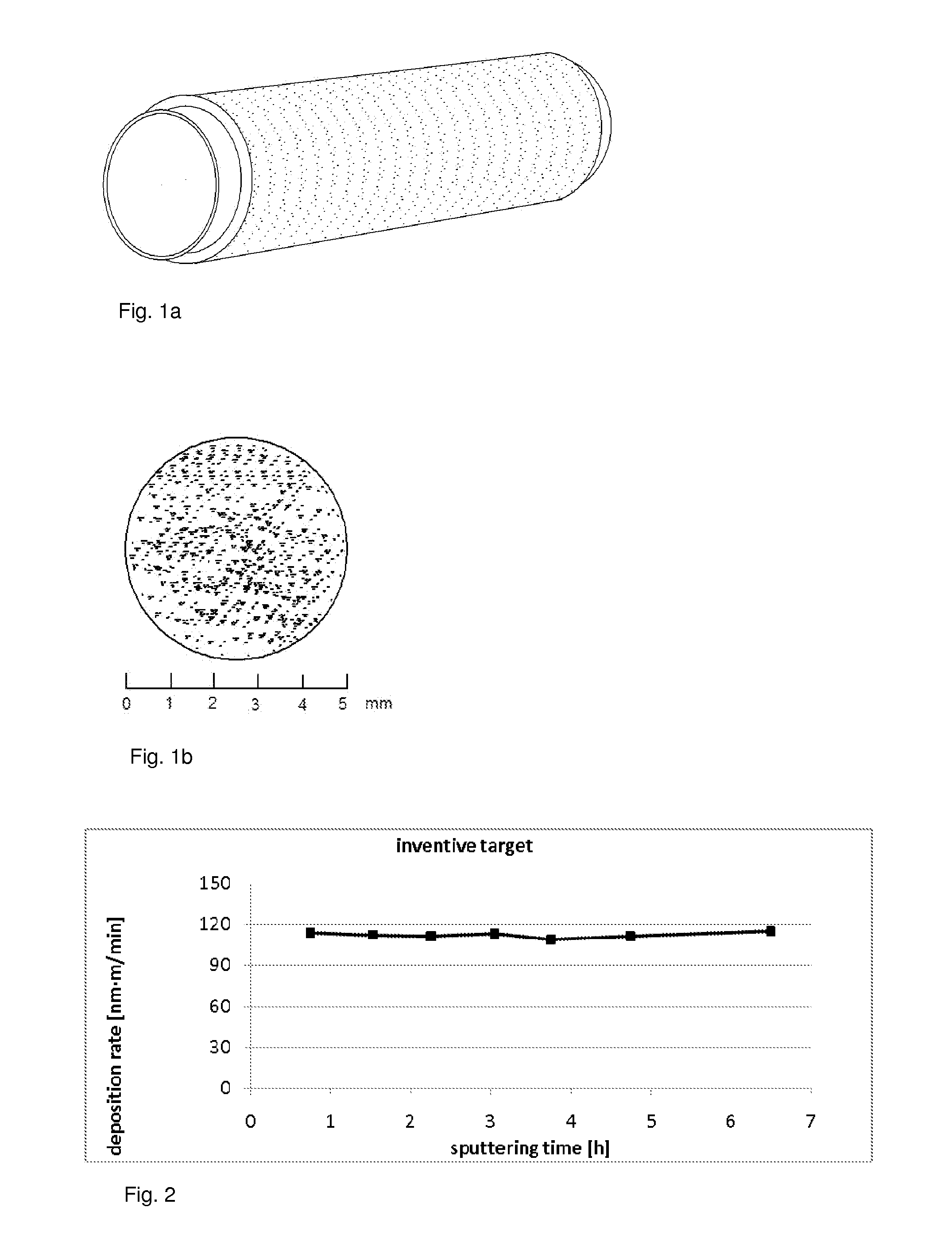
[0032]Highly pure indium (99.999%) was melted in a crucible. A carrier tube provided with a rough layer of adhesion promoter was mounted on a rotary device. The liquid melted indium metal was supplied by a feed line to an atomizer nozzle where it was sprayed by the action of a gas. The liquid melted drops hit the rotating carrier tube, and a relative motion of carrier tube versus spray nozzle thus caused thick metallic indium layer to be deposited in the form of multiple layers on the carrier tube over time.

[0033]The optimal temperature of the melt must be determined in some preliminary experiments as a function of nozzle geometry, spraying distance, and circumferential speed of the carrier tube. Temperatures in the range of 170-230° C. have proven to be beneficial.

[...


PUM

PropertyMeasurementUnit
mean grain sizeaaaaaaaaaa
grain sizeaaaaaaaaaa

Abstract

A tube-shaped sputtering target is provided having a carrier tube and an indium-based sputtering material arranged on the carrier tube. The sputtering material has a microstructure having a mean grain size of less than 1 mm, measured as the mean diameter of the grains on the sputtering-roughened surface of the sputtering material.

Description

BACKGROUND OF THE INVENTION[0001]The invention relates to a tube-shaped sputtering target having a carrier tube and an indium-based sputtering material arranged on the carrier tube.[0002]Indium tube targets are used, for example, for coating CuInGa absorber layers for thin layer photovoltaic cells based on CuInGaS2 or CuInGaSe2 (also referred to as “CIGS”). Indium sputtering is often associated with the formation of needle-shaped structures on the surface of the sputtering target, which lead to different sputtering rates and thus uneven thickness of layers as a function of grain orientation (M. Weigert, “The Challenge of CIGS Sputtering,” Heraeus Thin Film Materials magazine, No.11, April 2008).[0003]Thus far, the corresponding tube targets have been produced by a simple casting process, as is described, for example, in European Patent EP 1 186 682 B1. Owing to the metal needing to be very pure (99.99 to 99.999%) for the CIGS application, the sputtering targets have a very coarse st...

Claims


Application Information

Patent Timeline
Patent Type & Authority Applications(United States)
IPC IPC(8): B05D5/12B32B3/26B05D1/02
CPCC23C14/3414H01J37/342Y10T428/12396Y02E10/541C23C14/3407H01J37/3426C22C28/00C23C4/08C23C4/123C23C14/34
Inventor SIMONS, CHRISTOPHSCHLOTT, MARTINHEINDEL, JOSEFSTAHR, CHRISTOPH
Owner MATERION ADVANCED MATERIALS GERMANY GMBH
Why Eureka
Try Eureka