Multimodal Dynamic Robotic Systems

a robotic system and multi-modal technology, applied in the field of robotic mechanisms, can solve the problems of increasing the overall size and weight of the robot, and significant deficiencies of the wheeled mobile robot that have not been adequately overcome, so as to achieve the effect of moving and functioning efficiently

Active Publication Date: 2012-08-23
RGT UNIV OF CALIFORNIA
View PDF12 Cites 138 Cited by
  • Summary
  • Abstract
  • Description
  • Claims
  • Application Information

AI Technical Summary

Benefits of technology

[0008]It is an advantage of the present invention to provide a multimodal robot that can move and function efficiently on complex terrain and / or in harsh operating environments.
[0009]In an exemplary embodiment, the robotic systems according to the invention include a frame or body with two or more wheels rotatably mounted on the frame or body and a motor for independently driving each wheel. A system controller generates a signal for actuating each motor based on information provided by one or more sensors in communication with the system controller for generating feedback signals for providing reactive actuation of the motors for generating one or more functions selected from the group consisting of forward motion, backward motion, climbing, hopping, balancing, and throwing. A power source is included for providing power to operate the drive motors, system controller and the one or more sensors.
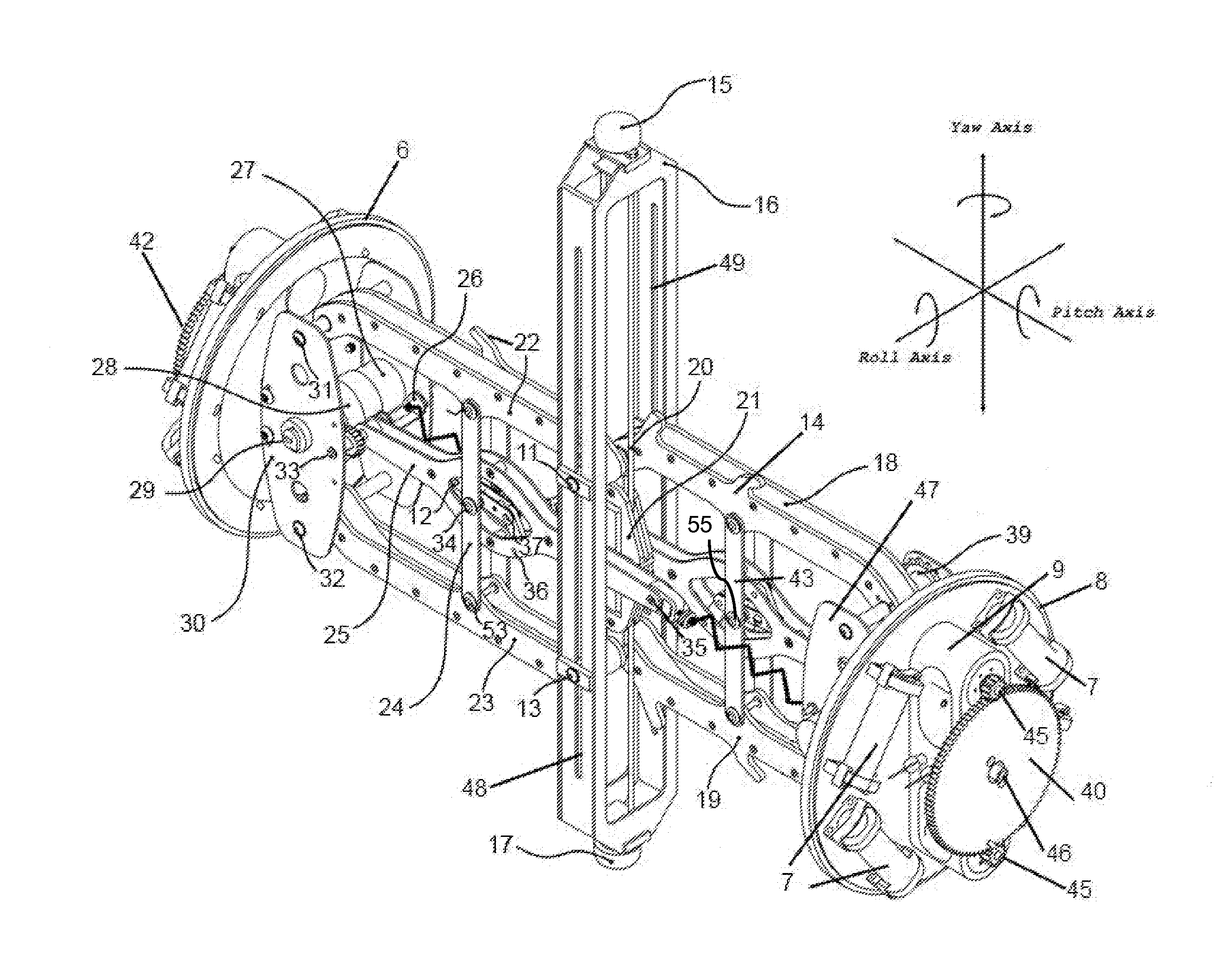
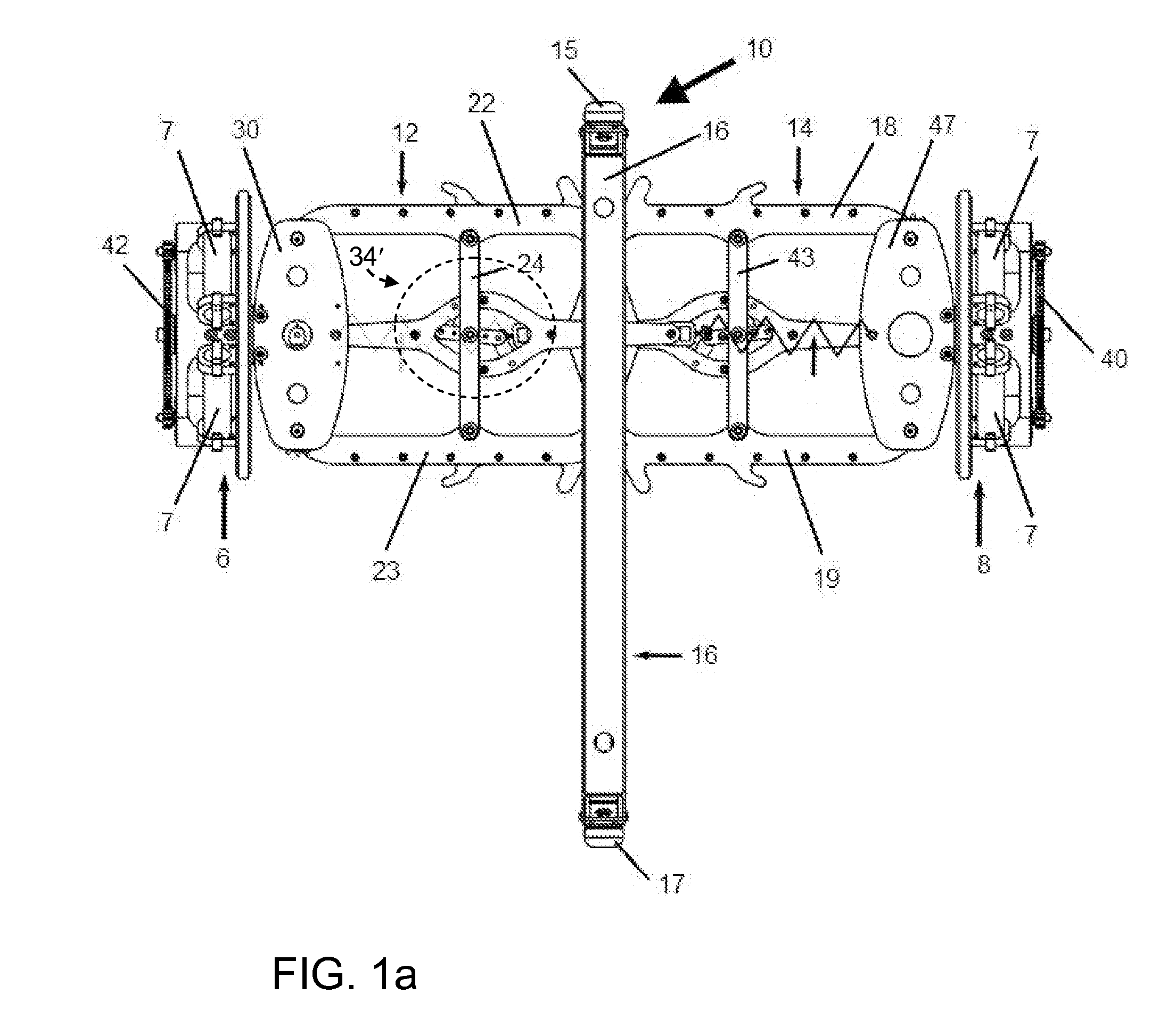
[0010]In one aspect of the invention, a robotic system according includes a frame with two or more wheels rotatably mounted thereon and a motor for independently driving each wheel. A system controller generates a signal for actuating each motor based on information provided by one or more sensors in communication with the system controller for generating feedback signals for providing reactive actuation of the motors for generating one or more functions selected from the group consisting of forward motion, backward motion, climbing, hopping, balancing, and throwing. A power source is included for providing power to operate the drive motors, system controller and the one or more sensors. The frame includes two arms, each having a distal end on which a wheel is mounted and a proximal end and a leg centrally disposed between the two arms with the proximal end of each arm rotatably attached to the leg. An arm motor is disposed on each arm for independently driving rotation of the arm relative to the leg, so that when the leg is disposed in a vertical orientation with an end of the leg in contact with a support surface, (i) downward symmetrical rotation of the arms positions the wheels in contact with the support surface for wheeled locomotion on the support surface, (ii) rapid upward symmetrical rotation of the arms lifts the leg off of the support surface to produce a hopping motion; and (iii) antisymmetrical rotation of the arms balances the frame on the end of the leg.
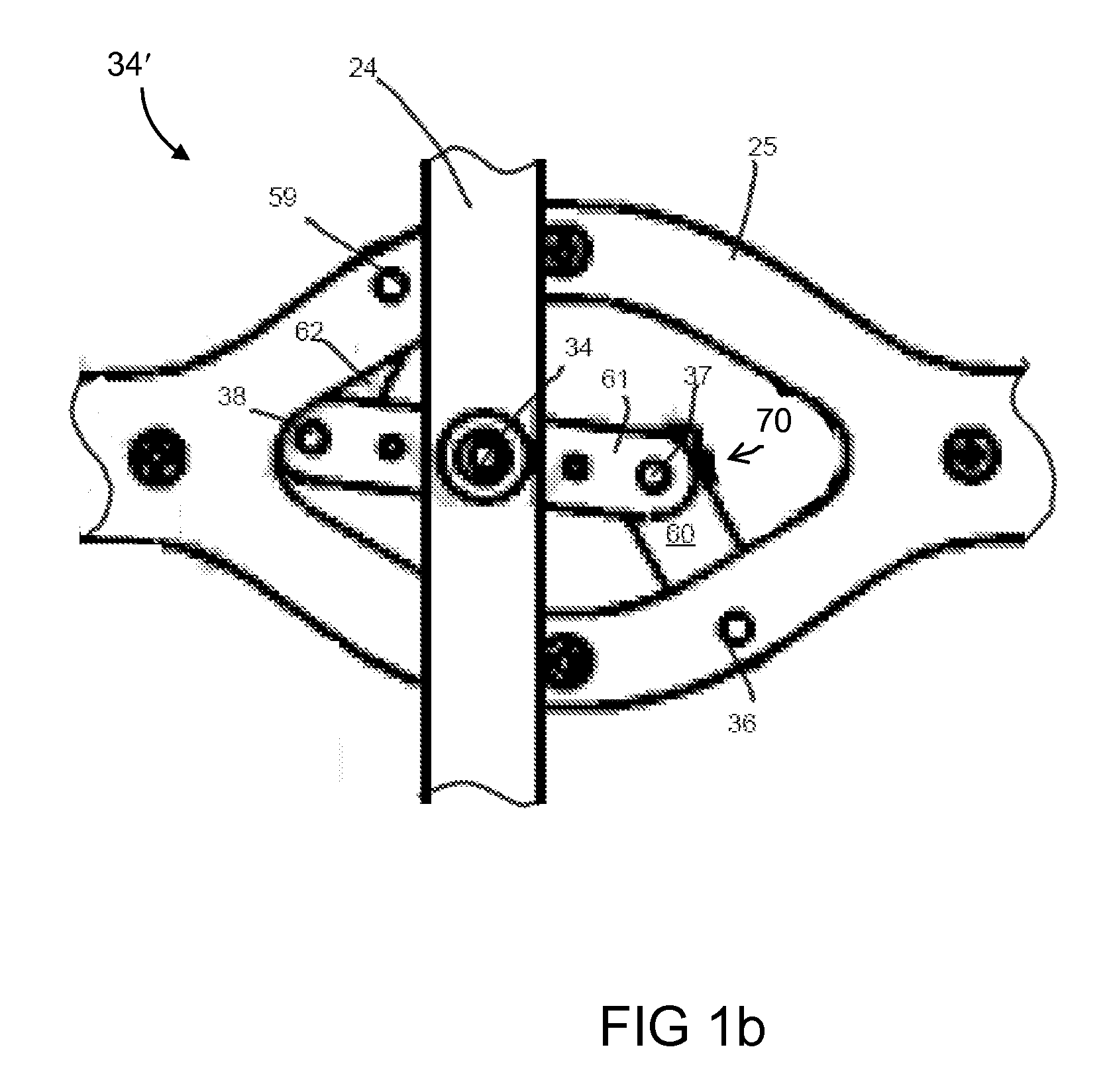
[0011]In another aspect of the invention, a robotic system according includes a body with two or more wheels rotatably mounted thereon and a motor for independently driving each wheel. A system controller generates a signal for actuating each motor based on information provided by one or more sensors in communication with the system controller for generating feedback signals for providing reactive actuation of the motors for generating one or more functions selected from the group consisting of forward motion, backward motion, climbing, hopping, balancing, and throwing. A power source is included for providing power to operate the drive motors, system controller and the one or more sensors. The body comprises a chassis having two drive wheels rotatably mounted on opposite sides thereof, each drive wheel disposed on an axle that is rotated by a corresponding drive motor for rotating the drive wheel. A pair of elongated arms is rotatably mounted on opposite sides of and perpendicular to the chassis, each arm having a proximal end disposed on a corresponding axle, and a distal end, on which a second wheel is mounted in a common plane with the corresponding drive wheel. A second motor is associated with each arm, and a linkage between the second motor and the axle for each arm causes the second motor, when activated, to rotate one of the chassis and the corresponding arm relative to the other. Independent activation of the second motor of both arms to rotate the arms symmetrically relative to the chassis shifts a center of gravity for balancing on one of the distal end or proximal end of the arms. The linkage between the second motor and the axle for each arm and a linkage between the drive motor and the drive wheel can be incorporated into a two-degree of freedom joint. In one embodiment, each arm supports a track.
[0012]In still another aspect of the invention, a robotic system according includes a body with two or more wheels rotatably mounted thereon and a motor for independently driving each wheel. A system controller generates a signal for actuating each motor based on information provided by one or more sensors in communication with the system controller for generating feedback signals for providing reactive actuation of the motors for generating one or more functions selected from the group consisting of forward motion, backward motion, climbing, hopping, balancing, and throwing. A power source is included for providing power to operate the drive motors, system controller and the one or more sensors. The body comprises a chassis having two drive wheels rotatably mounted on opposite sides thereof, attached to a corresponding drive motor for rotating the drive wheel. A pair of elongated drive arms is rotatably mounted on opposite sides of and perpendicular to the chassis, with each drive arm having a proximal end disposed on a corresponding axle, and a distal end which supports a second wheel in a common plane with the corresponding drive wheel. A boom arm comprising a weighted portion attached to connector arms that are pivotably mounted on each side of the chassis so that the weighted portion is disposed parallel to the chassis. At least one second motor is connected to the connector arms by a linkage such that activation of the at least one second motor rotates one of the chassis and the boom arm relative to the other. Independent activation of the at least one second motor shifts a center of gravity for balancing on one of the distal end or proximal end of the drive arms. The system controller controls the drive motors and the at least one second motor to reactively shift the center of gravity for stability. In one embodiment, each arm supports a track.
[0013]In another aspect of the invention, a robotic system according includes a frame with two or more wheels rotatably mounted thereon and a motor for independently driving each wheel. A system controller generates a signal for actuating each motor based on information provided by one or more sensors in communication with the system controller for generating feedback signals for providing reactive actuation of the motors for generating one or more functions selected from the group consisting of forward motion, backward motion, climbing, hopping, balancing, and throwing. A power source is included for providing power to operate the drive motors, system controller and the one or more sensors. The two or more wheels comprise a plurality of reaction wheels and the motor for driving each reaction wheel is disposed within a housing to define a plurality of momentum exchange elements mounted on one or more axes attached to the frame. The frame comprises a geometrical structure which allows the plurality of momentum exchange elements to be distributed about the frame to individually or simultaneously generate angular momentum in a plurality of different directions. In one variation, the one or more axes comprise a single gimbal axis, each having a corresponding gimbal motor. In another variation, the one or more axes comprise a double gimbal axis, each having two corresponding gimbal motors. A shell may be provided to enclose the frame and momentum exchange elements.

Problems solved by technology

Notwithstanding these developments, wheeled mobile robots have significant deficiencies that have not been adequately overcome.
For example, wheeled robots frequently have difficulty traversing rough terrain.
While this problem may be reduced by increasing the size of the wheels of the robot, increases in wheel size cause various undesirable consequences including an increase in the overall size and weight of the robot.
Further, increases in wheel sizes do not necessarily result in corresponding increases in operational features such as payload capacity.
Also, wheeled robots can be adversely affected by harsh operating environments such as heat, chemicals, and the like.

Method used


Image

  • Multimodal Dynamic Robotic Systems
  • Multimodal Dynamic Robotic Systems
  • Multimodal Dynamic Robotic Systems

Examples


first embodiment

[0090]The multimodal robot of the first embodiment can be fitted with optical, audio, thermal, chemical and other environmental sensors, or a combination of different sensors, which can be used to provide input into an adaptive system controller, e.g., artificial intelligence to allow the vehicle to develop a situational awareness that will permit predictive path planning in complex environments. Alternatively, or in addition, the vehicle can have incorporated into its electronics a transceiver for receiving remote commands and for transmitting information collected by its sensors.

[0091]The robotic system described herein is useful for maneuvering within complex structures or rugged terrain via different combinations of hopping, pole climbing, toe balancing, horizontal roving and uprighting, all in a controlled fashion. For example, the robotic system can climb stairs using a combination of pole climbing and toe balancing to climb stairs.

Second Multimodal Robot Embodiment

[0092]A sec...

second embodiment

[0104]The multi-modal robot of the second embodiment is capable of performing a wide variety of maneuvers with the minimal set of actuators, thus saving cost and weight. Additional sensors can be mounted internally or externally, such as contaminant sensors, Global Positioning System (GPS) receivers, wind sensors, analog or digital cameras, optical or radiation sensors, among many other possible uses. End effectors may be mounted on the mobile robot platform 104 or arms 110, 120 or 119, such as linkage mechanisms with a gripper, solid or liquid collection systems, lighting systems, or weapons systems, among many others.

[0105]An alternative configuration of the second multimodal robot embodiment is illustrated in FIGS. 16a-c. In this configuration, shifting of the center of gravity is still used, however the manner in which the shifting is effected is different.

[0106]In this embodiment, the robot includes a chassis 148 and an actuated boom 150. The chassis 148 is driven by a pair of ...

third embodiment

[0113]In a third embodiment, a spherical robot incorporates momentum exchange devices to achieve rapid acceleration or deceleration in any direction.

[0114]As illustrated in FIG. 23, an exemplary embodiment of the spherical robot according to the present invention includes a frame 202 for supporting a plurality of momentum-exchange elements 204 so that the elements are distributed relative to the surface of a spherical shell 210 that encloses the frame 202, elements 204, and all control electronics, actuators and batteries that are required to power and control the robot. Sensors may also be included to provide feedback to optimize balancing and locomotion under different conditions. The control electronics may include wireless communication devices for communication with a remote computer, mobile phone or other wireless device. Alternatively, the spherical robot may be tethered to a controller, such as a joystick, track ball or the similar external control device.

[0115]The basic ele...


PUM


Abstract

Robotic systems according to the invention include a frame or body with two or more wheels rotatably mounted on the frame or body and a motor for independently driving each wheel. A system controller generates a signal for actuating each motor based on information provided by one or more sensors in communication with the system controller for generating feedback signals for providing reactive actuation of the motors for generating one or more functions selected from the group consisting of forward motion, backward motion, climbing, hopping, balancing, throwing and catching. A power source is included for providing power to operate the drive motors, system controller and the one or more sensors.

Description

RELATED APPLICATIONS[0001]This application claims the priority of U.S. Provisional Applications No. 61 / 231,672, filed Aug. 6, 2009, and No. 61 / 324,258, filed Apr. 14, 2010, which are incorporated herein by reference.FIELD OF THE INVENTION[0002]The present invention relates to robotic mechanisms that exhibit multimodal capability including rolling, hopping, balancing, climbing, and picking up and throwing objects. More particularly, the invention relates to multimodal dynamic robotic systems that can move and function efficiently on complex terrain and / or in harsh operating environments.BACKGROUND OF THE INVENTION[0003]Robots have been developed for applications ranging from material transportation in factory environments to space exploration. One area in which mobile robots have been widely adopted is in the automobile industry, where robots transport components from manufacturing work stations to the assembly lines. These automated guided vehicles (AGVs) follow a track on the groun...

Claims


Application Information

Patent Timeline
Patent Type & Authority Applications(United States)
IPC IPC(8): B25J13/08B25J5/00
CPCB25J5/005B62D55/075B62D55/00B25J5/007B62D57/02Y10S901/01A63H17/266B60K7/00A63H17/262A63H15/06B62D37/00B25J9/1694
Inventor BEWLEY, THOMAS R.SCHMIDT-WETEKAM, CHRISTOPHERCAVENDER, ANDREWMOROZOVSKY, NICHOLASSAMS, BENJAMINCHEN, PO-TINGGRINBERG, MATT
Owner RGT UNIV OF CALIFORNIA
Why Eureka
Try Eureka