Method for simultaneously producing carbon nanotubes and hydrogen, and device for simultaneously producing carbon nanotubes and hydrogen

a technology of carbon nanotubes and hydrogen, which is applied in the direction of physical/chemical process catalysts, gas-gas reaction processes, cell components, etc., can solve the problems of short time that the catalyst remains in the reactor, poor space use in the reactor, and difficulty in increasing the spatial concentration of the catalyst, etc., to achieve efficient production, reduce the cost, and achieve the effect of large-scale production

Inactive Publication Date: 2012-08-30
THE UNIV OF TOKYO +1
View PDF4 Cites 41 Cited by
  • Summary
  • Abstract
  • Description
  • Claims
  • Application Information

AI Technical Summary

Benefits of technology

[0070]With the method for simultaneously producing carbon nanotubes and hydrogen according to the present invention, the following effects are achieved. That is, with the method for simultaneously producing carbon nanotubes and hydrogen according to the present invention, carbon nanotubes can be produced on a large scale and at low cost, and simultaneously, hydrogen can be efficiently produced. In addition, the production method of the present invention can use a support in which area per unit volume is large, and therefore, space utilization rate is high, and the production method of the present invention is suitable for the mass production of carbon nanotubes. In addition, the structure of such a support suppresses pressure loss and is suitable for feeding a gas at high speed. Therefore, it is possible to easily separate and recover the carbon nanotubes from the support by an unsteady gas pulse or a steady gas flow, and suppress the mixing of the catalyst into the produced carbon nanotubes.
[0071]In addition, by providing a method for resupporting a catalyst on the support, it is possible to repeatedly synthesize carbon nanotubes and hydrogen.

Problems solved by technology

But, since the catalyst is entrained in a reaction gas, time that the catalyst remains in the reactor is short, and the catalyst is mixed into the nanotubes, a product.
In addition, since the nanoparticles of the catalyst are as small as several nm, and aggregation is fast, it is difficult to increase the spatial concentration of the catalyst, and nanotube productivity per L of reactor volume is about 1 g/day.
But, since in the reactor, only a two-dimensional space which is a plane can be used, space use in the rea

Method used


Image

  • Method for simultaneously producing carbon nanotubes and hydrogen, and device for simultaneously producing carbon nanotubes and hydrogen
  • Method for simultaneously producing carbon nanotubes and hydrogen, and device for simultaneously producing carbon nanotubes and hydrogen
  • Method for simultaneously producing carbon nanotubes and hydrogen, and device for simultaneously producing carbon nanotubes and hydrogen

Examples


example 1

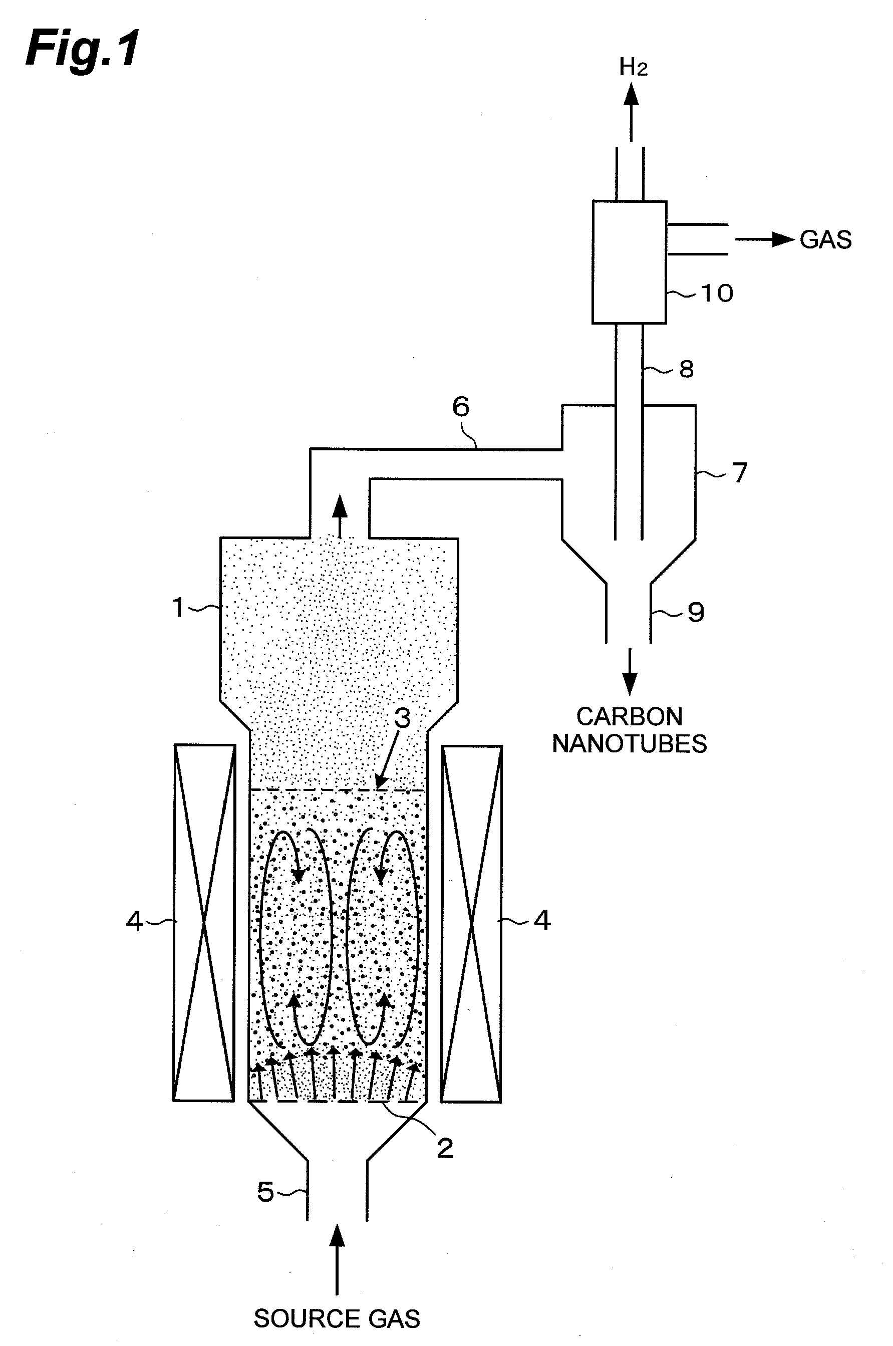
[0183]Example 1 of the present invention will be described. Here, alumina beads were used as a support, and an Al2O3 carrier was supported on the alumina beads. The Al2O3 carrier was sputtered on the alumina beads. The alumina beads had a diameter of 0.5 mm. The average film thickness of the Al2O3 carrier (carrier layer) was 15 nm. Then, Fe was supported on the Al2O3 carrier as a catalyst. This support was performed by sputtering-support. The Fe supported on the Al2O3 carrier had an average film thickness of 1.5 nm. This support was placed in a reactor, and while a source gas at atmospheric pressure with a 1.1 vol % C2H2 / 26 vol % H2 / 0.06 vol % H2O / Ar balance was fed to the reactor, carbon nanotubes and hydrogen were synthesized in a fluidized bed state.

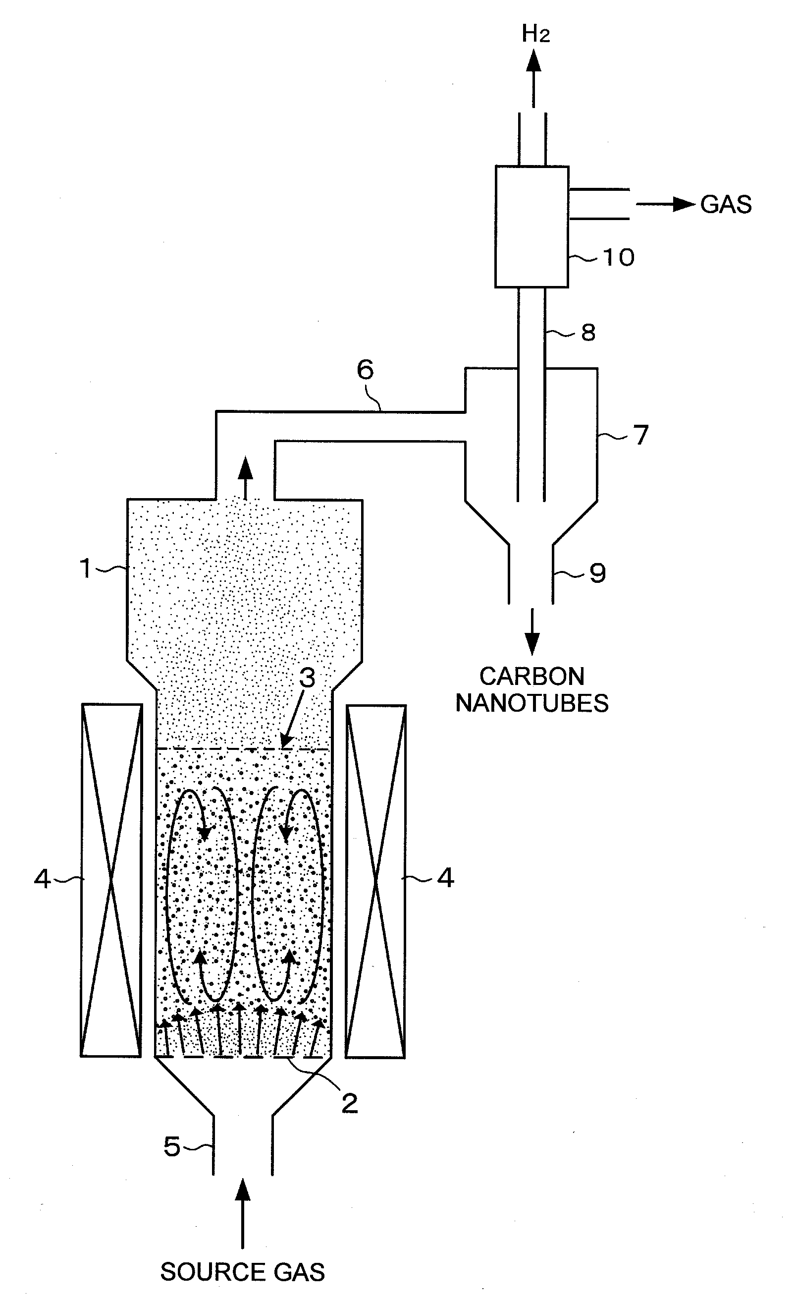
[0184]The reactor is made of quartz glass shown in FIG. 6, and is a vertical CVD reactor which can be used either as a fixed bed or as a fluidized bed. The temperature of a reaction portion in the reactor was 820° C. The feed of the s...

example 2

[0185]Example 2 of the present invention will be described. Here, alumina beads were used as a support. The alumina beads had a diameter of 0.5 mm. The alumina beads were impregnated with an aluminum nitrate aqueous solution, and then dried and fired to support an Al2O3 carrier on the alumina beads. The alumina beads on which the Al2O3 carrier was supported were impregnated with a ferric nitrate aqueous solution, and then dried and fired to support Fe particles on the Al2O3 carrier on the alumina beads. This support was placed in a reactor, and while a source gas at atmospheric pressure with a 1.1 vol % C2H2 / 26 vol % H2 / 0.06 vol % H2O / Ar balance was fed to the reactor, carbon nanotubes and hydrogen were synthesized in a fluidized bed state.

[0186]The reactor is made of quartz glass shown in FIG. 6, and is a vertical CVD reactor which can be used either as a fixed bed or as a fluidized bed. The temperature of a reaction portion in the reactor was 820° C. The feed of the source gas at ...

example 3

[0187]Example 3 of the present invention will be described. Here, alumina beads were used as a support. The alumina beads had a diameter of 0.5 mm. A reactor is one made of quartz glass shown in FIG. 6, and is a vertical CVD reactor which can be used either as a fixed bed or as a fluidized bed. The alumina beads were introduced into the reactor, and then, the reactor was heated to 820° C. and held. An aluminum isopropoxide vapor with Ar as a carrier gas was introduced into the reactor for 3 minutes to support an Al2O3 carrier layer on the alumina beads. Next, a ferrocene vapor with Ar as a carrier gas was introduced into the reactor for 1 minute to support Fe catalyst particles on the Al2O3 carrier layer.

[0188]Next, a source gas was fed onto the alumina beads on which the catalyst was supported, held in the reactor at high temperature, to perform the simultaneous synthesis of carbon nanotubes and hydrogen. The feed of the source gas at atmospheric pressure was performed in a feed am...


PUM

PropertyMeasurementUnit
Widthaaaaaaaaaa
Widthaaaaaaaaaa
Frequencyaaaaaaaaaa

Abstract

A method for simultaneously producing carbon nanotubes and hydrogen according to the present invention is a method for simultaneously producing carbon nanotubes and hydrogen, in which using a carbon source containing carbon atoms and hydrogen atoms and being decomposed in a heated state, and a catalyst for producing carbon nanotubes and H2 from the carbon source, the above carbon nanotubes are synthesized on a support in a heated state, placed in a reactor, and simultaneously, the above H2 is synthesized from the above carbon source, the method comprising a synthesis step of flowing a source gas comprising the above carbon source over the above support, on which the above catalyst is supported, to synthesize the above carbon nanotubes on the above support and simultaneously synthesize the above H2 in a gas flow.

Description

TECHNICAL FIELD[0001]The present invention relates to a method for simultaneously producing carbon nanotubes and hydrogen and an apparatus for simultaneously producing carbon nanotubes and hydrogen. More particularly, the present invention relates to a production method for mass-producing carbon nanotubes having various structures at a low cost and on a large scale and simultaneously producing hydrogen and an apparatus for simultaneously producing carbon nanotubes and hydrogen, used for the production method.BACKGROUND ART[0002]Carbon nanotubes are a material having a structure in which graphene sheets are rolled into a cylindrical shape and having a one-dimensional structure having a very large aspect ratio (see Non Patent Literature 1). The carbon nanotubes are known to have mechanically excellent strength and flexibility, semiconducting and metallic conductivity, and further, chemically very stable properties. For methods for producing carbon nanotubes, an arc discharge method, a...

Claims


Application Information

Patent Timeline
IPC IPC(8): D01F9/127D01F9/133B82Y30/00B82Y40/00
CPCB01J21/04Y02E60/13B01J37/0201B01J37/086B01J37/347B82Y30/00B82Y40/00C01B3/26C01B31/0206C01B2203/0277C01B2203/04C01B2203/085H01G11/36H01M4/587C01B31/024B01J23/745C01B32/15C01B32/16C01B32/164Y02E60/10B01J19/24
Inventor NODA, SUGURUKIM, DONG YOUNGOSAWA, TOSHIOSUGIME, HISASHIHASEGAWA, KEIHABA, EISUKE
Owner THE UNIV OF TOKYO
Why Eureka
Try Eureka