Cation exchange membrane, electrolysis vessel using the same and method for producing cation exchange membrane

Active Publication Date: 2012-09-20
ASAHI KASEI CHEM CORP
View PDF3 Cites 12 Cited by
  • Summary
  • Abstract
  • Description
  • Claims
  • Application Information

AI Technical Summary

Benefits of technology

[0023]According to the present invention, it is possible to provide the cation exchange membrane having excellent mechanical strength against fo

Problems solved by technology

However, the ion exchange membrane formed of such a fluorine-ba

Method used


Image

  • Cation exchange membrane, electrolysis vessel using the same and method for producing cation exchange membrane
  • Cation exchange membrane, electrolysis vessel using the same and method for producing cation exchange membrane
  • Cation exchange membrane, electrolysis vessel using the same and method for producing cation exchange membrane

Examples


example 1

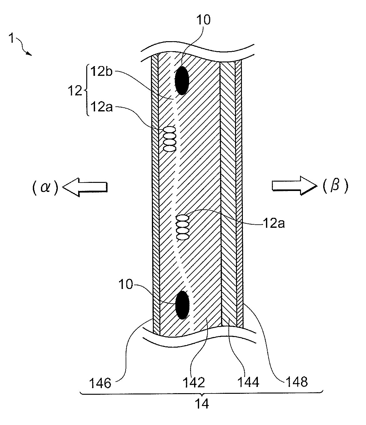
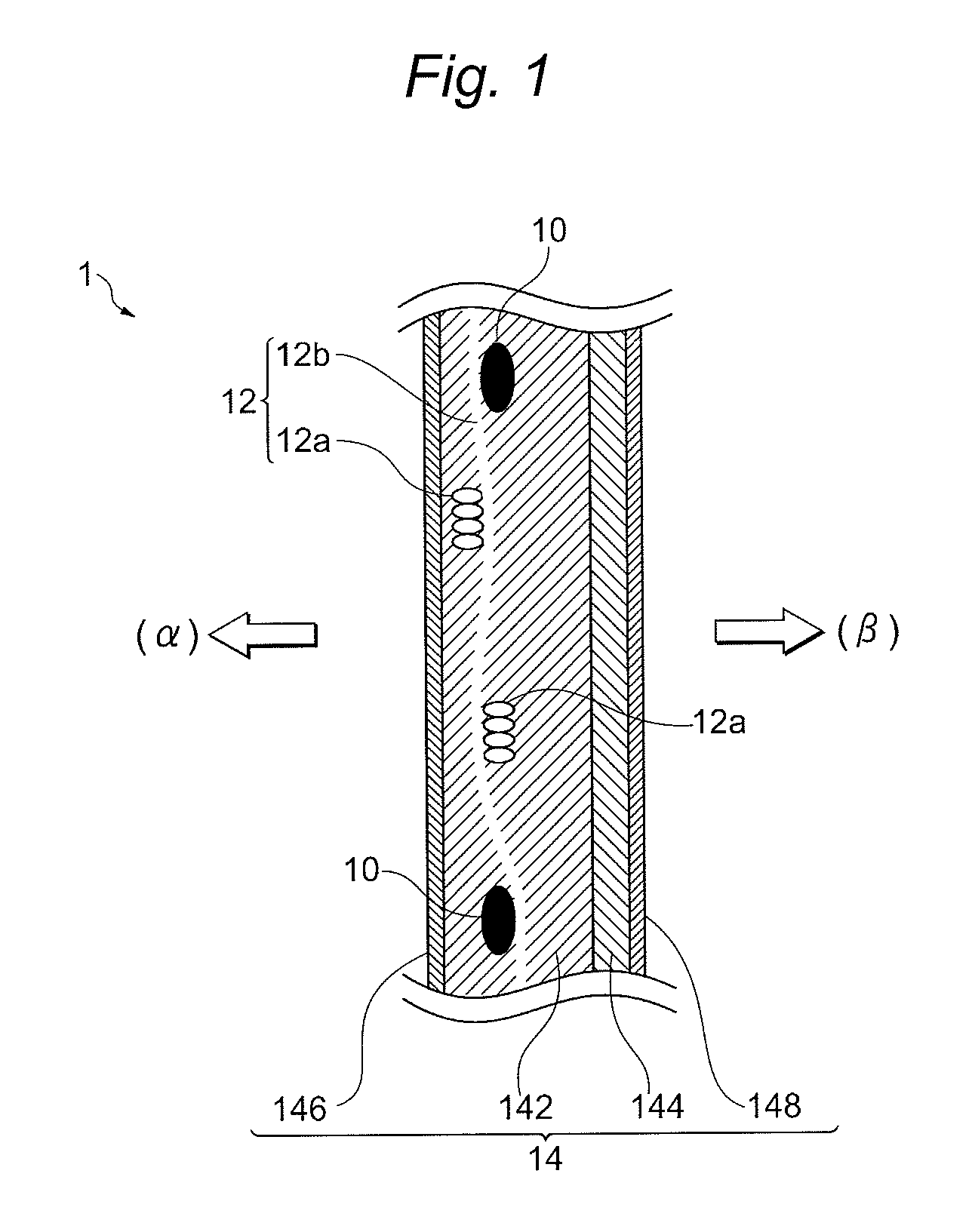
[0150]As a reinforcing core material, a monofilament of polytetrafluoroethylene (PTFE) of 90 deniers (hereinafter referred to as a “PTFE yarn”) was used. As a sacrifice yarn, a yarn of 6-filament polyethylene terephthalate (PET) of 40 deniers twisted at a rate of 200 times / m (hereinafter referred to as a “PET yarn”) was used. As a dummy yarn, a yarn of 15-filament polyvinyl alcohol (PVA) of 36 deniers twisted at a rate of 200 times / m (hereinafter referred to as a “PVA yarn”) was used.

[0151]First, PTFE yarns were arranged at a rate of 24 yarns / inch at approximately equal intervals. MD yarns were prepared by use of a continuous 3-dent reed as follows. A bundle of 2 yarns consisting of PTFE yarn and PET yarn was passed through a first reed; a bundle of 2 yarns consisting of PET yarn and PTFE yarn was passed through a second reed; and a bundle of 2 yarns consisting of PET yarn and PET yarn was passed through a third reed. The bundles of yarns in this combination were sequentially and re...

example 2

[0160]A cation exchange membrane was prepared by using the same materials as in Example 1 except that a yarn (PVA yarn) of 15-filament polyvinyl alcohol (PVA) of 28 deniers twisted 200 times / m was used as a dummy yarn.

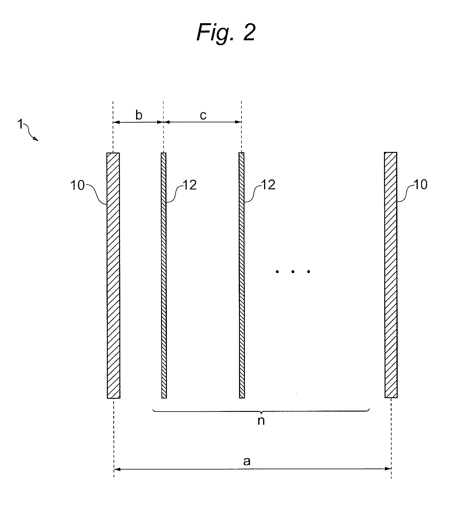
[0161]In the obtained cation exchange membrane, in the TD direction, the distance a2 between the reinforcing core materials adjacent to each other was 1005 μm, the number n of elution holes provided between the adjacent reinforcing core materials was 2 and the distance c2 of the adjacent elution holes was 373 μm. According to calculation, the distance c2 was expressed by 1.11a2 / (n+1) (see FIG. 8, the same hereinafter).

[0162]Furthermore, in the TD direction, in the distance a1 between the reinforcing core materials adjacent to each other of 1091 μm, the number n of elution holes provided between the adjacent reinforcing core materials was 2 and the distance c1 of the adjacent elution holes was 252 μm. According to calculation, the distance c1 was expressed by 0.69a1 / (n+...

example 3

[0166]First, PTFE yarns were arranged at a rate of 24 yarns / inch at approximately equal intervals. MD yarns were prepared by use of a continuous 3-dent reed as follows. A bundle of 2 yarns consisting of PTFE yarn and PET yarn was passed through a first reed; a bundle of 2 yarns consisting of PET yarn and PTFE yarn was passed through a second reed; and a bundle of 2 yarns consisting of PET yarn and PET yarn was passed through a third reed. Weaving of the bundles of yarns in this combination was repeated in this order to obtain a plain weave. As to TD yarns, PTFE yarn, PVA yarn, PVA yarn, PET yarn, PET yarn, PVA yarn and PVA yarn were arranged in this order repeatedly and at approximately equal intervals to obtain a plain weave. In this manner, a woven fabric (reinforcing material) was obtained. Subsequently, the obtained reinforcing material was subjected to contact bonding performed by a roll heated to 125° C. Thereafter, the reinforcing material was soaked in a 0.1 N aqueous sodium...


PUM

PropertyMeasurementUnit
Volumeaaaaaaaaaa
Distanceaaaaaaaaaa

Abstract

A cation exchange membrane includes: a membrane body containing a fluorine-based polymer having an ion-exchange group; and two or more reinforcing core materials arranged approximately in parallel within the membrane body. The membrane body is provided with two or more elution holes formed between the reinforcing core materials adjacent to each other. A distance between the reinforcing core materials adjacent to each other is represented by a, a distance between the reinforcing core materials and the elution holes adjacent to each other is represented by b, a distance between the elution holes adjacent to each other is represented by c, and the number of the elution holes formed between the reinforcing core materials adjacent to each other is represented by n. The relationship represented by the following expression (1) or expression (2) are satisfied:
b>a/(n+1)  (1);
c>a/(n+1)  (2)

Description

TECHNICAL FIELD[0001]The present invention relates to a cation exchange membrane, an electrolysis vessel using the same and a method for producing the cation exchange membrane.BACKGROUND ART[0002]A fluorine-containing ion exchange membrane is excellent in e.g., heat resistance and chemical resistance. Therefore, the fluorine-containing ion exchange membrane has been used not only as a cation exchange membrane for alkali chloride electrolysis for producing chlorine and an alkali but also a diaphragm for generating ozone, a fuel cell, wide variety of diaphragms for electrolysis such as water electrolysis and hydrochloric acid electrolysis. Of them, the membrane for use in alkali chloride electrolysis is demanded to, e.g., increase current efficiency in view of productivity, reduce electrolysis voltage in view of economic efficiency and reduce the concentration of sodium chloride in caustic soda in view of quality of a product.[0003]Of these demands, in order to increase current effici...

Claims


Application Information

Patent Timeline
IPC IPC(8): C25B13/04D06Q1/02C25B9/08C25B9/19
CPCC25B13/02C25B13/08H01M2300/0082H01M8/1023H01M8/1039Y02E60/521H01M8/106H01M8/1062H01M8/1067H01M8/1079H01M8/1053C08J5/2206C08J2327/12B01J47/12B01J39/20H01M8/1076C09K13/00Y02E60/50Y02P70/50
Inventor KAMEYAMA, HIROYUKISUGIMOTO, MANABUKADO, YOSHIFUMI
Owner ASAHI KASEI CHEM CORP
Why Eureka
Try Eureka